
Coding apparatus, coding method and recording medium having coded program recorded therein, and decoding apparatus, decoding method and recording medium having decoded program recorded therein

a technology of coding apparatus and recording medium, which is applied in the direction of coding, error correction/detection using turbo codes, and phase-modulated carrier systems. it can solve the problems of large circuit scale, poor performance, and complicated constitution of various parts. achieve the effect of high performan

Inactive Publication Date: 2005-05-31
SONY CORP
View PDF7 Cites 19 Cited by
  • Summary
  • Abstract
  • Description
  • Claims
  • Application Information

AI Technical Summary

Benefits of technology

[0071]The present invention has been accomplished in view of the actual conditions as noted above. It is an object of the present invention to provide a coding apparatus capable of carrying out coding and decoding under the high performance, a coding method and a recording medium having a coded program recorded therein, and a decoding apparatus, a decoding method and a recording medium having a decoded program recorded therein.
[0072]A coding apparatus according to the present invention for achieving the aforementioned object is a coding apparatus for carrying out serially concatenated coded modulation with respect to data input comprising a first coding means for carrying out coding whose code rate is k/(k+1) with respect to data of k-bit input; a interleaving means for interleaving order of bits constituting data comprising a bit series of (k+1) bits coded by the first coding means; a second coding means serially concatenated with the interleaving means to carry out coding whose code rate is 1 with respect to data of (k+1) bit input; and a mapping means for mapping data of (k+1) bit coded by the second coding means to a transmission symbol of a predetermined modulation system, wherein the interleaving means interleaves order of bits so that at least a part of weights with respect to data comprising a bit series of (k+1) bit supplied from the first coding means are coded by the second coding means; the second coding means makes as small as possible the total value of the hamming distance of input bits between passes to be the minimum Euclidean distance with respect to data of (k+1) bit supplied from the interleaving means; and the mapping means causes the hamming distance of input bits in the second coding means to correspond to a small one as the distance between signal points on the I/Q plane is smaller to apply mapping to data of (k+1) bit supplied from the second coding means.
[0073]Further, a coding method according to the present invention for achieving the aforementioned object is a coding method for carrying out serially concatenated coded modulation with respect to data input comprising a first coding step for carrying out coding whose code rate is k/(k+1) with respect to data of k-bit input; an interleaving step for interleaving order of bits constituting data comprising a bit series of (k+1) bits coded by the first coding step; a second coding step for carrying out coding whose code rate is 1 with respect to data of (k+1) bit rearranged by the interleaving step and input; and a mapping step for mapping data of (k+1) bit coded by the second coding step to a transmission symbol of a predetermined modulation system, wherein the interleaving step interleaves order of bits so that at least a part of weights with respect to data comprising a bit series of (k+1) bit supplied from the first coding step are coded by the second coding step; the second coding step makes as small as possible the total value of the hamming distance of input bits between passes to be the minimum Euclidean distance with respect to data of (k+1) bit supplied from the interleaving step; and the mapping step causes the hamming distance of input bits in the second coding step to correspond to a small one as the distance between signal points on the I/Q plane is smaller to apply mapping to data of (k+1) bit supplied from the second coding step.
[0074]Furthermore, a decoding apparatus according to the present invention for achieving the aforementioned object is a decoding apparatus for decoding of codes subjected to serially concatenated coded modulation generated by coding equipment, the coding equipment comprises a first coding means for carrying out coding whose code rate is k/(k+1) with respect to data of k-bit input; a first interleaving means for interleaving order of bits constituting data comprising a bit series of (k+1) bits coded by the first coding means; a second coding means serially concatenated with the first interleaving means to carry out coding whose code rate is 1 with respect to data of (k+1) bit input; and a mapping means for mapping data of (k+1) bit coded by the second coding means to a transmission symbol of a predetermined modulation system, wherein the first interleaving means interleaves order of bits so that at least a part of weights with respect to data comprising a bit series of (k+1) bits supplied from the first coding means are coded by the second coding means; the second coding means makes as small as possible the total value of the hamming distance of input bit between passes to be the mini

Problems solved by technology

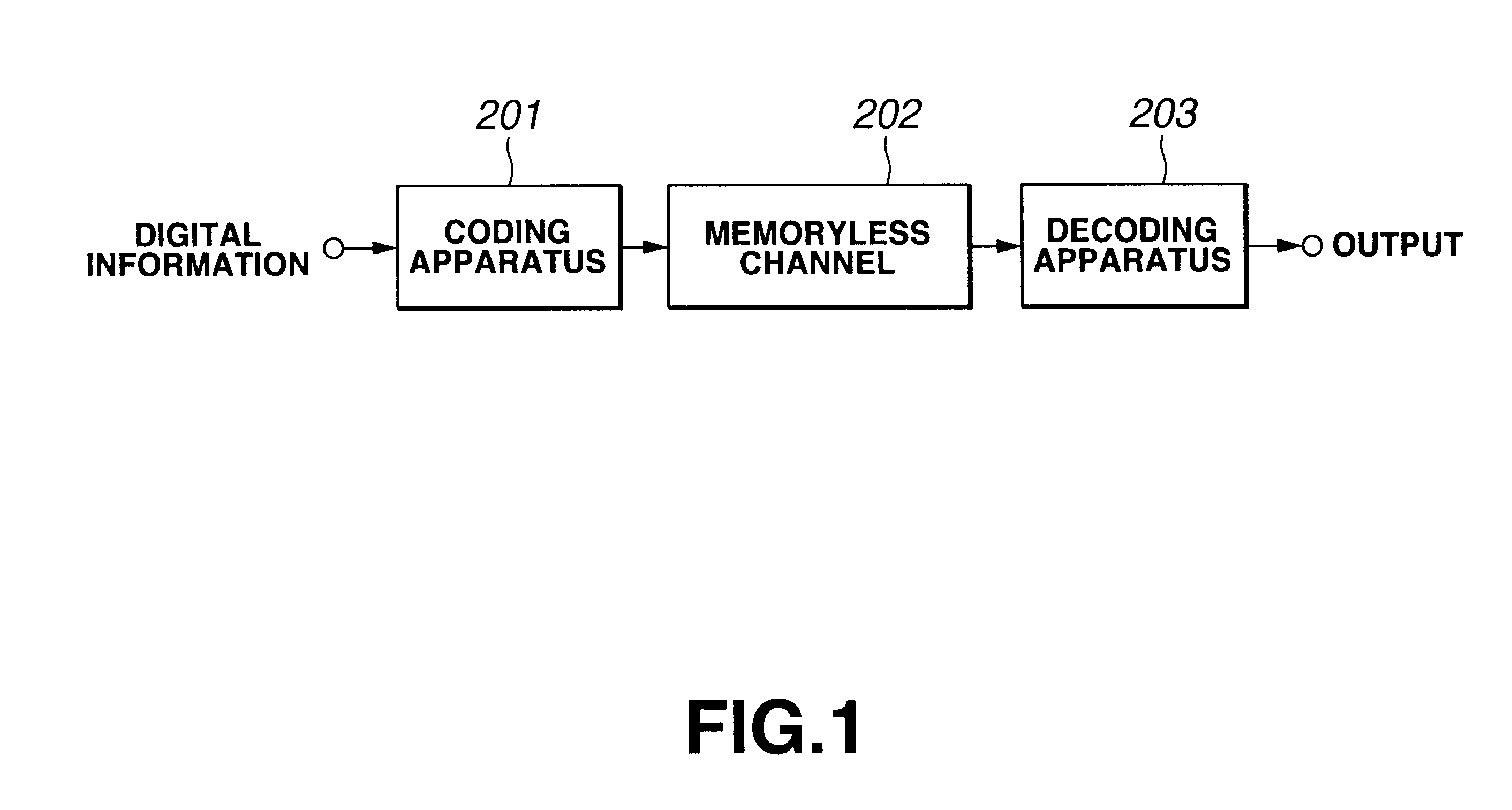
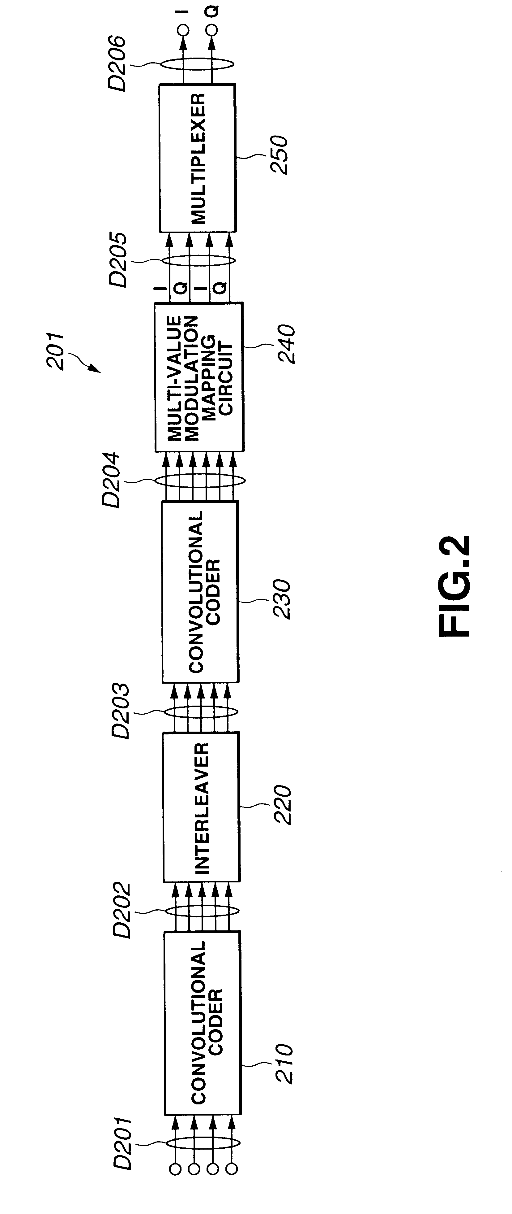
Incidentally, the coding apparatus 201 has a problem, since there are many bits need be processed in various parts, of bringing forth complicatedness of constitution of various parts and making a circuit scale huge.
As described above, the system composed of the coding apparatus 401 and the decoding apparatus 403 is able to carry out error correction coding and decoding rate as compared with the system composed of the coding apparatus 201 and the decoding apparatus 203, but poses a problem that the performance is somewhat poor.

Method used


Image

  • Coding apparatus, coding method and recording medium having coded program recorded therein, and decoding apparatus, decoding method and recording medium having decoded program recorded therein
  • Coding apparatus, coding method and recording medium having coded program recorded therein, and decoding apparatus, decoding method and recording medium having decoded program recorded therein
  • Coding apparatus, coding method and recording medium having coded program recorded therein, and decoding apparatus, decoding method and recording medium having decoded program recorded therein

Examples


Embodiment Construction

[0109]Preferred embodiments to which is applied the present invention will be described in detail with reference to the accompanying drawings.

[0110]This embodiment is concerned with a data transmit-receive system applied to a communication model in which as shown in FIG. 13, digital information is coded by a coding apparatus 1 provided on a transmission apparatus not shown, output of which is input into a receiving apparatus not shown through a memoryless channel 2 with noises, and the output is decoded by a decoding apparatus 3 provided on the receiving apparatus.

[0111]In the data transmit-receive system, the coding apparatus 1 carries out coding according to a serial concatenated trellis coded modulation, which is hereinafter referred to as SCTCM, system, in which as a first coding of a code (hereinafter referred to as an outer code), a convolutional operation whose code rate is “2 / 3” is carried out, and as a second coding of a code (hereinafter referred to as an inner code), a co...


PUM


Abstract

To carry out error correction coding and decoding according to a serially concatenated coded modulation system with a small circuit scale and high performance. A coding apparatus 1 is designed so that an interleaver 20 interleaves order of bits so that all weights are coded by a convolutional coder 30 with respect to data comprising a series of 3 bits supplied from a convolutional coder 10; the convolutional coder 30 makes as small as possible the total value of the hamming distance of input bit between passes to be the minimum Euclidean distance with respect to data of 3 bits supplied from the interleaver 20; and a multi-value modulation mapping circuit 40 causes the hamming distance of input bits in the convolutional coder 30 as the distance between signal point on the I / Q plane is smaller to subject data of 3 bits supplied from the convolutional coder 30 to mapping.

Description

BACKGROUND OF THE INVENTION[0001]1. Field of the Invention[0002]The present invention relates to a coding apparatus for carrying out serial concatenated trellis coded modulation, a coding method and a recording medium having a coded program recorded therein, and a decoding apparatus for decoding data subjected to serial concatenated trellis coded modulation, a decoding method and a recording medium having a decoded program recorded therein.[0003]2. Description of Related Art[0004]Lately, the study on, for example, a communication field such as a mobile communication and a deep space communication, a broadcasting field such as terrestrial wave or satellite digital broadcasting, and a magnetic, light or photo-electro recording field has been progressed materially, but with this, the study on a code theory for the purpose of making error correction coding and decoding efficient has been carried out actively.[0005]As a theoretical limit of code performance, a Shannon limit implied by a ...

Claims


Application Information

Patent Timeline
IPC IPC(8): H03M13/00H03M13/25H03M13/45H03M13/29G06F11/10H03M13/27H04L1/00H04L27/00H04L27/18
CPCH03M13/256H03M13/3988H03M13/2972H03M13/258
Inventor HATTORI, MASAYUKIMURAYAMA, JUNMIYAUCHI, TOSHIYUKIYAMAMOTO, KOUHEIYOKOKAWA, TAKASHI
Owner SONY CORP
Learn More