Device comprising a plurality of analysis sites on a support

a technology of analysis site and support, which is applied in the direction of biomass after-treatment, laboratory glassware, instruments, etc., can solve the problems of large device limitation, infinite reduction of drop b>7/b>, and very small quantity of reagent after drying

Inactive Publication Date: 2005-06-07
COMMISSARIAT A LENERGIE ATOMIQUE ET AUX ENERGIES ALTERNATIVES
View PDF14 Cites 50 Cited by
  • Summary
  • Abstract
  • Description
  • Claims
  • Application Information

AI Technical Summary

Benefits of technology

[0022]2) it allows the use of droplets having a greater diameter than that of the microdishes which gives a higher concentration of solute after evaporation of the solvent.
[0023]According to a first embodiment of the device of the invention, the side walls, the bottom parts and the edges of the microdishes are made in the same hydrophilic material. This makes it possible, in particular, to ensure refocusing and anchoring of the reagent drops in the microdishes and on the edge of the microdishes if the drop overflows the microdish.

Problems solved by technology

This device is considerably limited by the fact that reagent dispensers do not allow the size of drop 7 to be infinitely reduced.
Therefore, if the effective surface area of the site is reduced, the quantity of reagent after drying becomes very small.
Finally, handling the carrier with drops deposited on its surface is not easy.

Method used


Image

  • Device comprising a plurality of analysis sites on a support
  • Device comprising a plurality of analysis sites on a support
  • Device comprising a plurality of analysis sites on a support

Examples


first embodiment

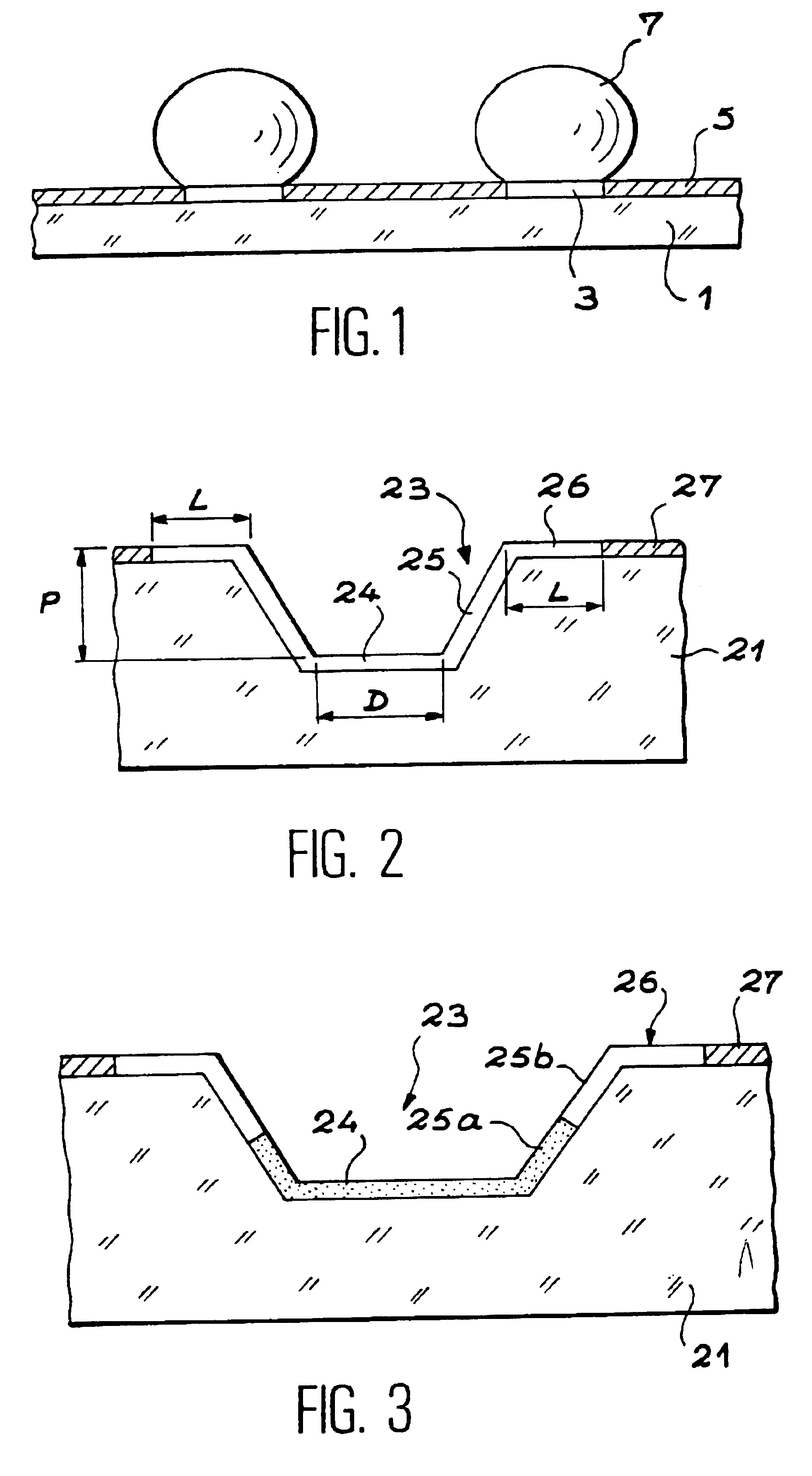
[0093]FIG. 2 shows the device of the invention, in which a single hydrophilic material is used.

[0094]In this figure, carrier 21 can be seen in which the microdishes 23 are hollowed out and have a flattened cone shape whose smaller base corresponds to the bottom 24 of the microdish. In the first embodiment of the invention, bottom parts 24, side walls 25 and the areas of the carrier surface surrounding each microdish, hereinafter called edges 26 of the microdishes, are formed of hydrophilic material, whereas the surface of the carrier located between the edges of the microdishes is formed of hydrophobic material 27.

second embodiment

[0095]FIG. 3 is a diagram of the device of the invention, in which two different hydrophilic materials are used.

[0096]In this figure the same references are used to designate the carrier 21, the microdishes 23 and the areas of hydrophobic material 27. In this case, the bottoms 24 of the microdishes and part of their side walls 25a are made in a first hydrophilic material whereas the remainder of their side walls 25b and the edges 26 are made in a second hydrophilic material. This makes it possible, as will be seen later, to achieve adhesion of the chemical or biological reagent to the bottom of the microdishes.

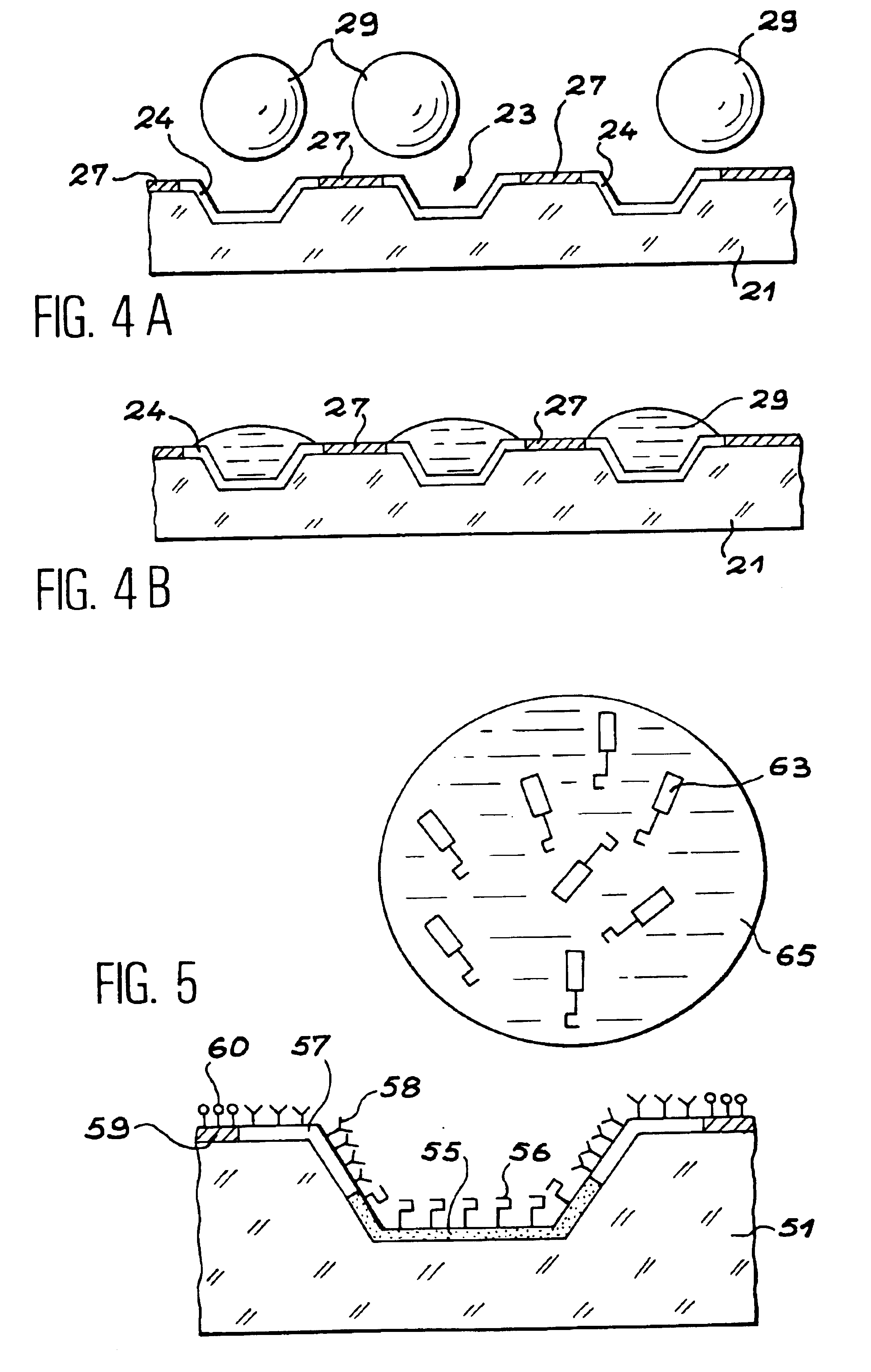
[0097]In these two embodiments of the device of the invention, the three-dimensional structuring of the carrier leads to obtaining numerous advantages.

[0098]With this structuring it is possible to limit the surface of the reactive sites corresponding to the opening of the microdishes, since the latter are hollowed in the thickness of the carrier and can contain more reagent or...


PUM

PropertyMeasurementUnit
depthaaaaaaaaaa
depthaaaaaaaaaa
depthaaaaaaaaaa

Abstract

The subject of the invention is a device for chemical or biological analysis comprising a carrier (21) containing a plurality of analysis sites able to fix a chemical or biological reagent, in which the analysis sites are formed of microdishes (23) hollowed out of the carrier, the side walls and the bottom of the microdishes and the areas of the carrier surface surrounding each microdish, called microdish edges, being made in at least one hydrophilic material (24), and the planar areas of the carrier arranged between the areas surrounding the microdishes being made in a hydrophobic material (27).
Drops (29) of reagent are therefore guided into the microdishes (23) on account of the hydrophobic areas (27). It is therefore possible to increase the density of analysis sites on the carrier.

Description

TECHNICAL FIELD[0001]The subject of the present invention is a device for chemical or biological analysis comprising a large number of analysis sites, which can be used in particular for pharmacological screening and for biological DNA tests.[0002]For screening, on a carrier containing a large number of sites covered with the same reagent, the effect of different molecules must be determined which are selectively deposited on each site in sequential manner.[0003]For biological testing, such as DNA tests, each site of the device is covered with a different DNA probe and the analyte, whose genomic sequence it is desired to determine, is placed in contact at the time of analysis with all the sites.[0004]In analytical chemistry, there is also a strong demand for the miniaturisation of dishes for chemical reaction (or chemical reactors).[0005]For all these applications, it is therefore important to have available a carrier containing the greatest possible number of analysis sites, but a ...

Claims


Application Information

Patent Timeline
Patent Type & Authority Patents(United States)
IPC IPC(8): G01N33/50C12M1/00C12M1/34C12N15/09C12Q1/00C40B60/14G01N33/15G01N33/53G01N33/543
CPCB01J2219/00317B01J2219/00605B01J2219/00612B01J2219/00617B01J2219/00619B01J2219/00621B01J2219/00653B01J2219/00659C12Q1/001C40B60/14G01N33/5438
Inventor CAILLAT, PATRICEROSILIO, CHARLES
Owner COMMISSARIAT A LENERGIE ATOMIQUE ET AUX ENERGIES ALTERNATIVES
Why Eureka
Try Eureka