Two-layer imageable element comprising thermally reversible polymers

a polymer and imageable technology, applied in the field of two-layer imageable elements, can solve the problems that none of the above references discloses the use of these polymers in thermal imaging, and achieve the effects of strong bonding, long press life, and increased resistance to press chemicals

Inactive Publication Date: 2005-06-07
KODAK POLYCHROME GRAPHICS
View PDF23 Cites 23 Cited by
  • Summary
  • Abstract
  • Description
  • Claims
  • Application Information

AI Technical Summary

Benefits of technology

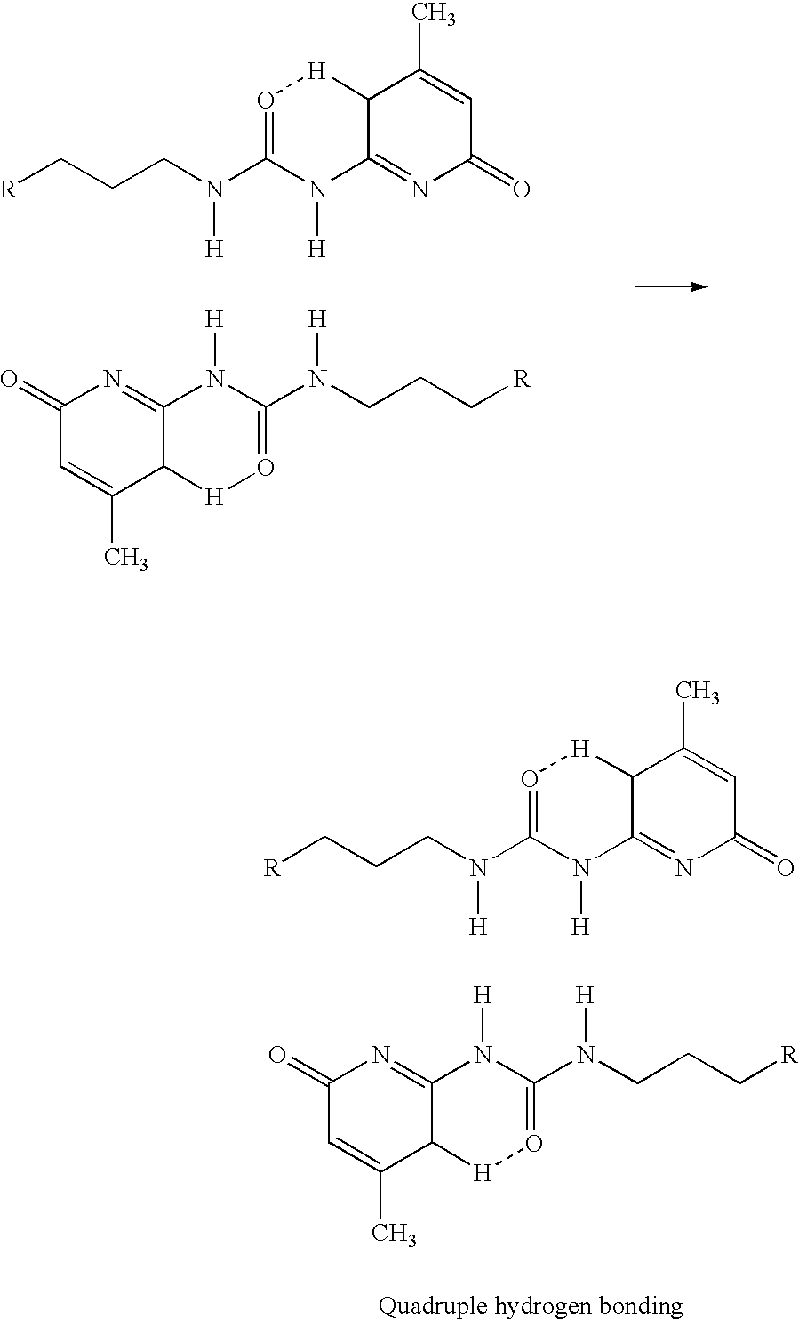
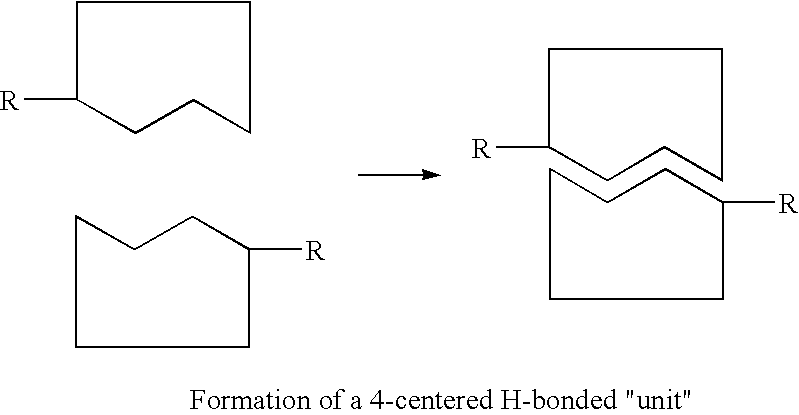
[0026]In the present invention, the image areas are reinforced with strong two or more centered H-bond links. Therefore, the image areas exhibit long press life and increased resistance to press chemicals when compared with the systems of the prior art, which include relatively weak single H-bond units. Thus, the thermally reversible polymers of the present invention can have relatively strong bonds and provide thermal solubilization systems that have enhanced differentiation between exposed and non-exposed areas. These polymers can undergo thermal solubilization and provide a durable, non-exposed area, corresponding to the etch resist in a PCB or to the image area in a printing plate.
[0027]The two-layer thermal positive working “computer-to-plate” systems, here after “CTP plates,” according to the present invention have excellent solvent resistance, high run lengths and wide developer latitudes. The imagewise exposure and development steps of the present invention do not require an intermediate pre-development heating step. In addition, superior press life is achieved without the need of a post-development bake because of the strength of the two or more centered H-bond links, such as, 4-centered H-bond units, in the image areas. The superior press life resulting from the strongly bonded image is unexpected for a two-layer, no-preheat, digitally imaged composition. In addition, the inventive element of the present invention is relatively simple to manufacture. Accordingly, the present invention provides thermally reversible polymers that can be used in simple and cost effective methods that are useful in thermal imaging of lithographic plates and circuit boards.

Problems solved by technology

None of the above references discloses the use of these polymers in thermal imaging.

Method used


Image

  • Two-layer imageable element comprising thermally reversible polymers
  • Two-layer imageable element comprising thermally reversible polymers
  • Two-layer imageable element comprising thermally reversible polymers

Examples


Embodiment Construction

[0028]Lithographic printing is based on the immiscibility of oil and water. Ink receptive areas are generated on the surface of a hydrophilic surface. When the surface is moistened with water and then ink is applied, the hydrophilic background areas retain the water and repel the ink. The ink receptive areas accept the ink and repel the water. The ink is transferred to the surface of a material upon which the image is to be reproduced. Typically, the ink is first transferred to an intermediate blanket, which in turn transfers the ink to the surface of the material upon which the image is thereafter reproduced.

[0029]Lithographic printing plate precursors, i.e., imageable elements, typically include a radiation-sensitive coating applied over the hydrophilic surface of a support material. If after exposure to radiation, the exposed regions of the coating become soluble and are removed in the developing process, revealing the underlying hydrophilic surface of the support, the plate is c...


PUM

PropertyMeasurementUnit
timeaaaaaaaaaa
dwell timeaaaaaaaaaa

Abstract

The present invention includes a two-layer imageable element, including: a substrate, a top layer including a first thermally imageable composition including (a) a first thermally sensitive supramolecular polymer or (b) a thermally imageable composition free of the first thermally sensitive supramolecular polymer; and disposed between the substrate and the top layer, a bottom layer including a second thermally imageable composition, which includes a second thermally sensitive supramolecular polymer. The present invention also includes a method of producing the imaged element.

Description

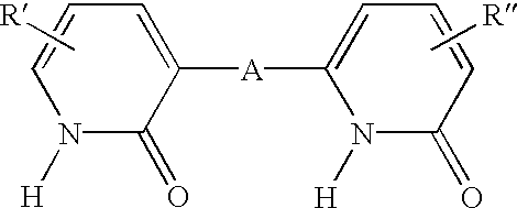
[0001]This application is a Continuation-In-Part and claims priority from U.S. application Ser. No. 09 / 751,650, filed Dec. 29, 2000, now U.S. Pat. No. 6,506,536.BACKGROUND OF THE INVENTION[0002]1. Field of the Invention[0003]The present invention relates to a two-layer imageable element including a substrate, a top layer including a first thermally imageable composition including a first thermally sensitive supramolecular polymer; and disposed between the substrate and the top layer, a bottom layer including a second thermally imageable composition including a second thermally sensitive supramolecular polymer. The thermally sensitive supramolecular polymer, which includes at least one covalently bonded unit and at least one thermally reversible non-covalently bonded unit that includes a two or more centered H-bond within each non-covalently bonded unit. More particularly, the present invention relates to a method of producing a two-layer imaged element.[0004]2. Description of the Pr...

Claims


Application Information

Patent Timeline
Patent Type & Authority Patents(United States)
IPC IPC(8): B41M5/36B41C1/10C08G73/06C08G73/00C08G73/02G03F7/039C08G18/28C08G18/38C08G18/54
CPCB41C1/1008C08G18/285C08G18/3848C08G18/542C08G73/0273C08G73/0694B41C2210/266Y10S430/146Y10S430/106Y10S430/109Y10S430/11Y10S430/145Y10S430/165Y10S430/111Y10S430/107B41C2210/02B41C2210/06B41C2210/14B41C2210/22B41C2210/24B41C2210/26B41C2210/262B41C2210/264B41C1/1016C08G83/008C09D163/00C08L101/00
Inventor ASAWA, YASUHIROISHIZUKA, YASUHIROHAYAKAWA, EIJIPAPPAS, S. PETER
Owner KODAK POLYCHROME GRAPHICS
Why Eureka
Try Eureka