Chip type capacitor, method for preparing the same and anode terminal used for preparing the same

a solid electrolytic capacitor and chip-type technology, applied in the field of chip-type solid electrolytic capacitors, can solve the problems of capacitors with insufficient bond strength, and inability to provide stably sufficient diffusion layers, etc., to achieve enhanced reliability and enhanced reliability

Inactive Publication Date: 2005-06-07
TOKIN CORP
View PDF12 Cites 41 Cited by
  • Summary
  • Abstract
  • Description
  • Claims
  • Application Information

AI Technical Summary

Benefits of technology

[0025]By employing the method, the protrusion of the anode terminal heated into a melt by the heating means such as a laser beam, an ion beam, arc discharge or the like is effectively supplied to gaps between the anode lead wire and the recess and the upper surface portion of the anode lead wire. Consequently, the extending portion of the anode lead wire has such a site that about 75% or more of a periphery of a section thereof in the direction substantially perpendicular to the extending direction of the anode lead wire is covered with solidified matter resulting from solidification of the melt derived from the protrusion of the anode terminal. The chip type capacitor having such a structure is less likely to have “open defectiveness” and has enhanced reliability.
[0026]According to a further embodiment of the present invention, there is provided a method for preparing a chip type capacitor comprising a solid electrolytic capacitor element having an anode lead wire partially extending therefrom; said method using an anode terminal having a recess for resting the extending portion of the anode lead wire and at least one protrusion located beside the recess and above the level of the top of the extending portion of the anode lead wire when the extending portion is rested thereon, said method comprising: resting the extending portion of the anode lead wire on the recess in such a manner that the anode lead wire is substantially perpendicular to the recess of the anode terminal; melting the

Problems solved by technology

However, the above-mentioned method does not always provide a sufficient surface area of the bond between the anode lead wire and the anode terminal.
Further, the method does not stably provide a sufficient diffusion layer formed including a bond

Method used


Image

  • Chip type capacitor, method for preparing the same and anode terminal used for preparing the same
  • Chip type capacitor, method for preparing the same and anode terminal used for preparing the same
  • Chip type capacitor, method for preparing the same and anode terminal used for preparing the same

Examples


example 1

[0132]Through the following procedure, a chip type capacitor which was not yet subjected to a step of sheathing by molding (a semifinished chip type capacitor) was prepared.

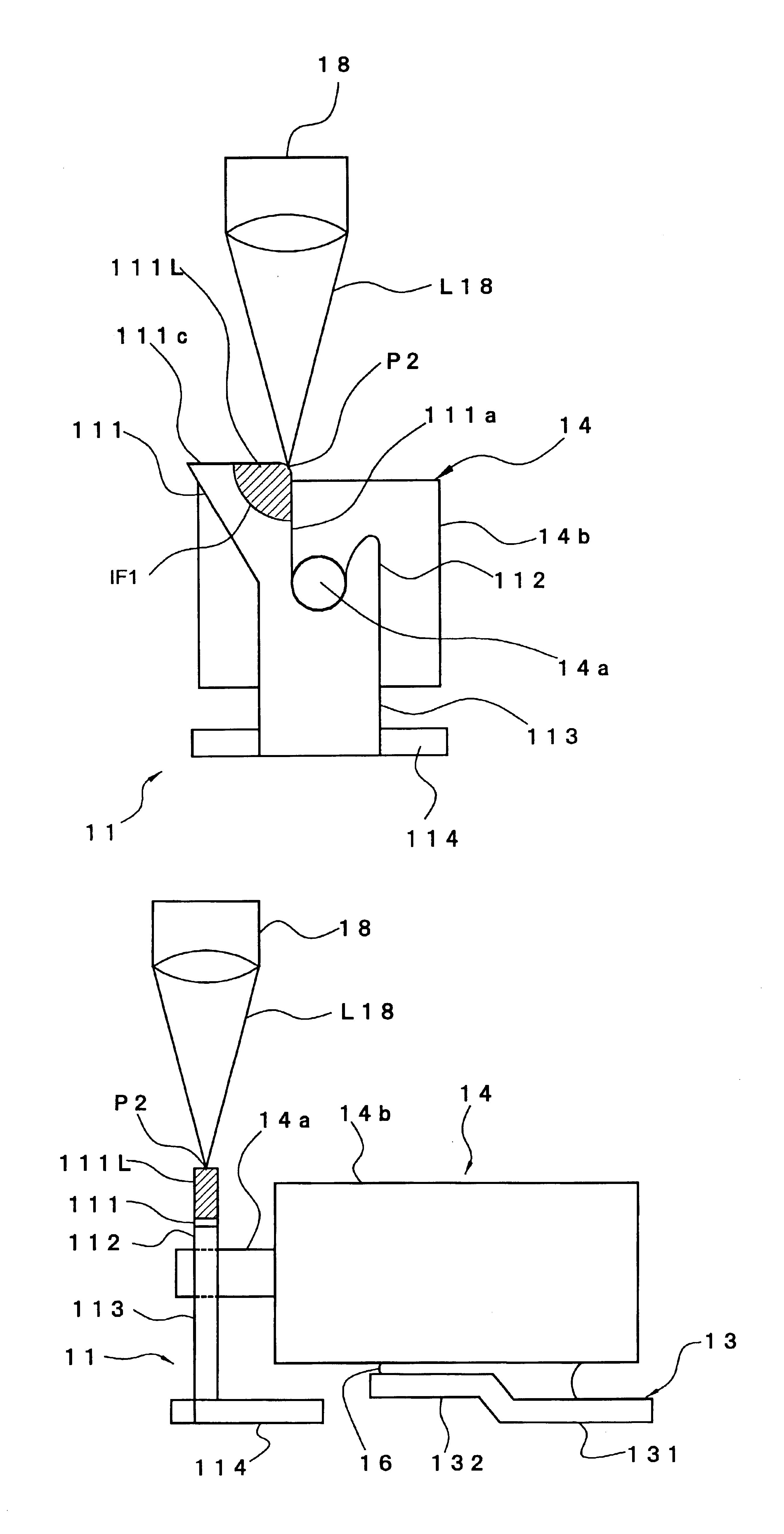
[0133]Using conventional technique, a capacitor element having a Ta anode body was prepared which had a rectangular paralellepipedonal shape of 1.6 mm in length, 0.85 mm in width and 0.8 mm in height and which is provided with a Ta anode lead wire having a diameter of 0.15 mm.

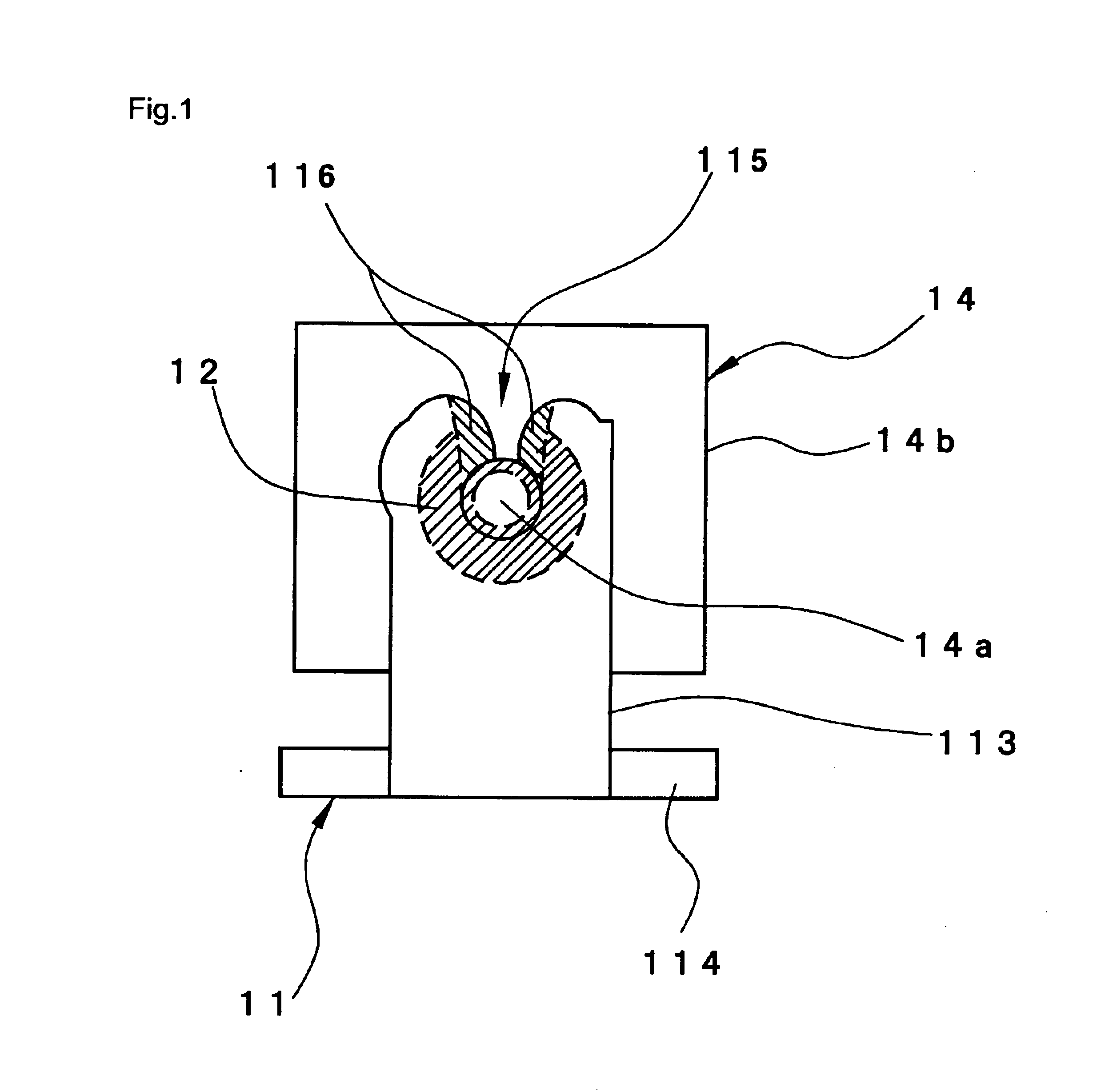
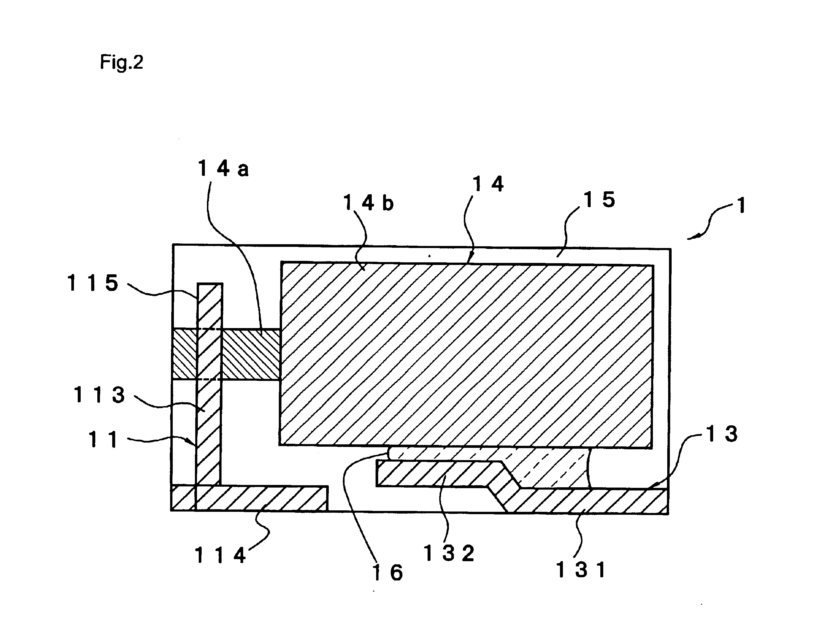
[0134]On the other hand, an anode terminal having a shape as shown in FIGS. 3 to 5 and a cathode terminal having a shape as shown in FIG. 2 were prepared. Each of them was made of a nickel(42%)-iron alloy plate (solder-plated). Specific dimensions with respect to the protrusion of the anode terminal were as follows.

[0135](i) width W1: 0.1 mm

[0136](ii) height H1: 0.24 mm

[0137](iii) width W2: 0.3 mm

[0138](iv) width W3: 0.15 mm (+allowance of 0.01 mm)

[0139](v) thickness t of the plate: 0.08 mm

[0140]Then, the Ta capacitor element and the cathode...

example 2

[0145]Each of semifinished chip type capacitors were prepared in the same manner as in Example 1 except that a top end surface of a protrusion and an anode lead wire were irradiated with a laser beam by scanning the laser beam.

[0146]In any of the thus obtained 33 semifinished chip type capacitors, a melt was supplied to the intended place.

[0147]With respect to the semifinished chip type capacitors, average percentage of covering the periphery of the section of the anode lead wire in the direction substantially perpendicular to the extending direction of the anode lead wire with the solidified matter resulting from the solidification of the melt of the protrusion of the anode terminal was about 95%.


PUM


Abstract

A chip type capacitor which has improved bond strength between an anode lead wire and an anode terminal and enhanced reliability, and a method for preparing the chip type capacitor and an anode terminal. The chip type capacitor has a solid electrolytic capacitor element including an element body having an anode body, a dielectric and a cathode body, and an anode lead wire partially extending from the anode body of the element body. An anode terminal is electrically connected to the portion of the anode lead wire extending from the anode body. This extending portion of the anode lead wire has about 75% or more of its periphery, in the direction substantially perpendicular to the extending direction of the anode lead wire, covered with solidified matter resulting from solidification of a melt, thereby bonding the anode terminal and the anode lead wire to each other.

Description

BACKGROUND OF THE INVENTION[0001]1. Field of the Invention[0002]The present invention relates to a chip type solid electrolytic capacitor, a method for preparing the same, and an anode terminal used in the preparation method.[0003]2. Description of the Related Art[0004]A chip type solid electrolytic capacitor (hereinafter often referred to simply as “chip type capacitor”) is in the form of a chip comprising, as its core, a capacitor element having an anode-dielectric-cathode structure. More specifically, the capacitor element has a structure comprising an anode made of a metal exhibiting valve action (valve metal), an oxidized layer as a dielectric layer formed over the surface of the anode, an electrolyte layer formed on the dielectric layer, and a cathode in the form of an electrically conductive layer formed on the electrolyte layer.[0005]In this connection, the valve metal means a metal capable of forming an oxidized layer whose thickness can be controlled by anodic oxidation. S...

Claims


Application Information

Patent Timeline
IPC IPC(8): H01G9/00H01G9/012H01G13/00
CPCH01G9/012H01G4/236H01G2/02
Inventor SANO, MITSUNORIKONO, TAKASHI
Owner TOKIN CORP
Why Eureka
Try Eureka