Interference canceller device and radio communication device

a technology of interference canceller and radio communication device, which is applied in the direction of amplitude demodulation, line-fault/interference reduction, baseband system details, etc., can solve the problems of increasing the cost of the system, and achieve the effect of simplifying the structure of the interference canceller and reducing the cost of the radio communication devi

Inactive Publication Date: 2005-06-07
FUJITSU LTD
View PDF12 Cites 38 Cited by
  • Summary
  • Abstract
  • Description
  • Claims
  • Application Information

AI Technical Summary

Benefits of technology

[0023]An object of the present invention is to simplify the structure of the ...

Problems solved by technology

However, a mere application of the array antenna to the DS-CDMA system to form the adaptive array receiver device makes the structure very complex and thus increases the cost of the system.
Particularly, the complex structure ...

Method used


Image

  • Interference canceller device and radio communication device
  • Interference canceller device and radio communication device
  • Interference canceller device and radio communication device

Examples


first embodiment

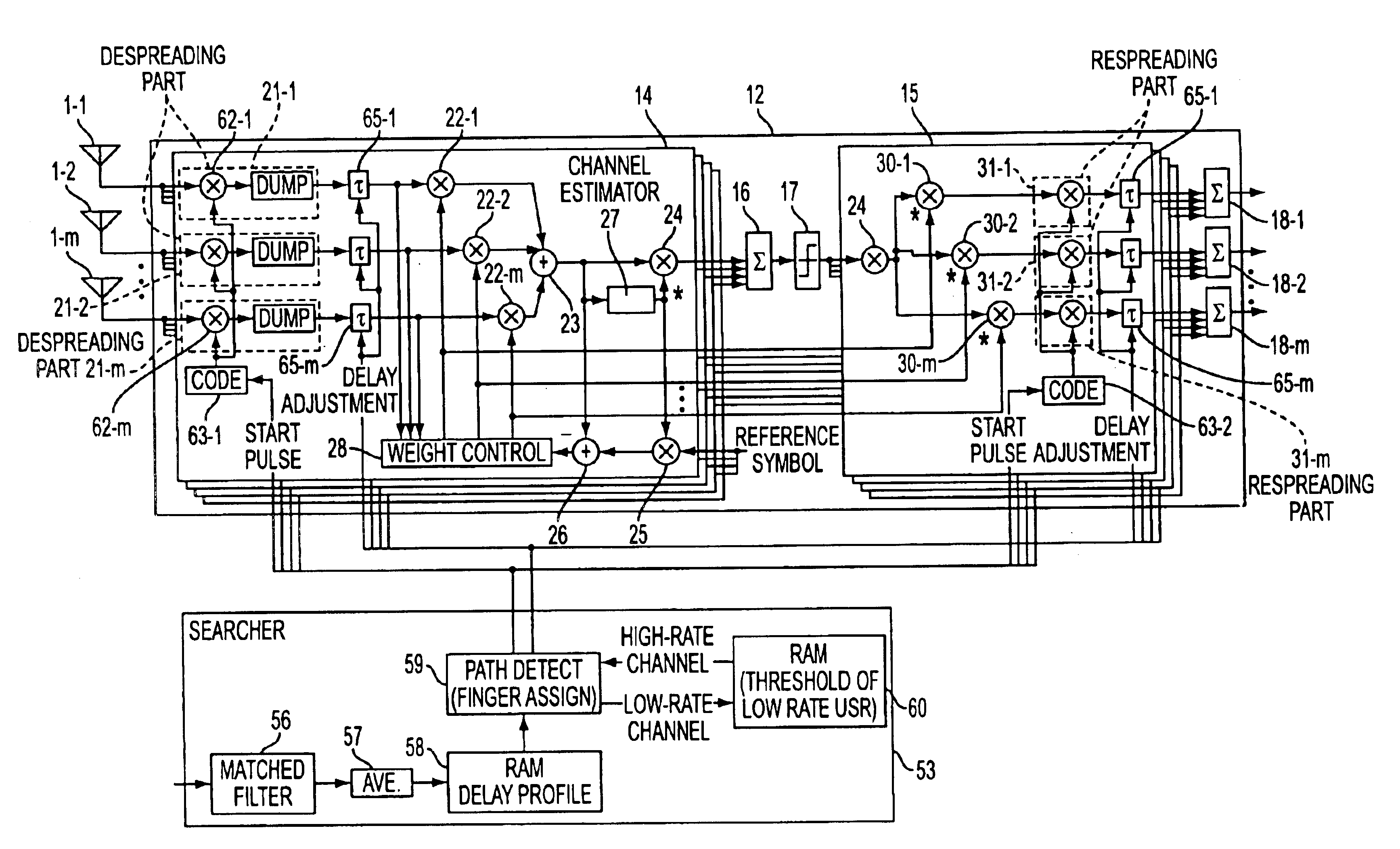
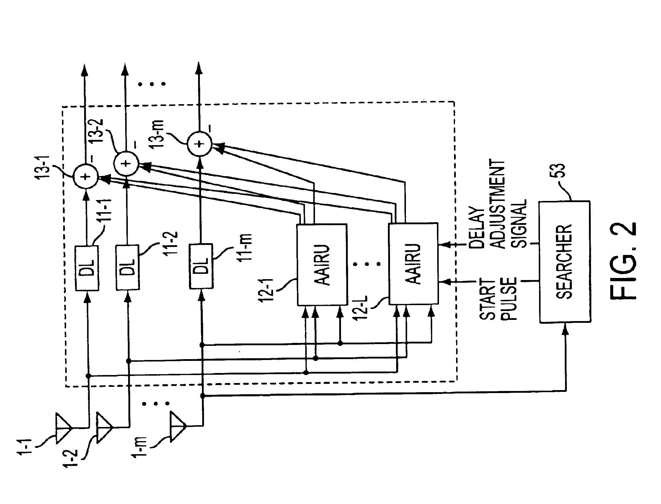
[0063]FIG. 6 shows a radio communication according to the present invention. The structure shown in FIG. 6 corresponds to a receiver part of the base station in the DS-CDMA system, wherein the structure shown in FIG. 2 is applied to the receiver part. In FIG. 6, reference numbers 1-1-1-m indicate array antenna elements, 11-1-11-m indicate delay circuits (DL), 12-1-12-L array antenna interference replicating units (AAIRU) for the high-rate channels, 13-1-13-m indicate adders, 60-1-60-k indicate adaptive array receivers (AA receivers) for low-rate users, and 61 indicates an interference canceller.

[0064]The array antenna interference replicating units 12-1-12-L have the structure shown in FIG. 3, and create interference replicas of the high-rate channels. The adders 13-1-13-m subtract the interference replicas d from the received signals obtained via the delay circuits 11-1-11-m. As have been described previously, the delay circuits 11-1-11-m compensate for delays in time caused by the...

second embodiment

[0066]FIG. 7 shows a radio communication device according to the present invention. The structure shown in FIG. 7 is simpler than that shown in FIG. 6. In FIG. 7, reference numbers 71-1-71-m indicate array antenna elements, 72 indicates an interference canceller, 73 indicates a delay circuit (DL), 74-1-74-L indicate array antenna interference replicating units ((AAIRU), 75 indicates an adder, and 76-1-76-k indicate receivers of low-rate users.

[0067]The signals received via the array antenna elements 71-1-71-m are input to the array antenna interference replicating units 74-1-74-L. The signal received via the array antenna element 71-1 is input to the receivers 76-1-76-k, via the delay circuit 73 and the adder 75. The adder 75 subtracts the interference replicating d from the array antenna interference replicating units 74-1-74-L from the signal obtained via the delay circuit 73, so that interference of the high-rate channels having high transmission power are eliminated. The interfe...

third embodiment

[0068]FIG. 8 shows a radio communication device according to the present invention. In this figure, reference numbers 81-1-81-m indicate array antenna elements, 82 indicates an interference canceller, 83-1-83-m indicate delay circuits (DL), 84-1-84-L indicate array antenna interference replicating units (AAIRU), 85-1-85-m indicate adders, 86-1-86-k indicate adaptive array receivers (AA receivers) for low rate users, and 87-1-87-L indicate adaptive array receivers (AA receivers) for high-rate users.

[0069]The array antenna interference replicating units 84-1-84-L have a structure similar to that of the array antenna interference replicating units in the aforementioned embodiments of the present invention. Signals received via the array antenna elements 81-1-81-m are applied to the array antenna interference replicating units 84-1-84-L. Hence, interference replicas of the high-rate channels and symbol replicas are created. The interference replicas thus created are respectively applied...


PUM


Abstract

The present invention is directed to an interference canceller for a DS-CDMA communication system and a radio communication device that performs multi-rate transmission and eliminates interference of high-rate channels by a simplified structure. In a DS-CDMA communication system that performs a multi-rate transmission including at least low-rate channels and high-rate channels, there is provided an interference canceller that includes an array antenna interference replicating unit. The interference replicating unit is used in high-rate channels that receive signals received via array antenna elements and creates interference replicas of the high-rate channels. The system also includes an adder 6, which subtracts the interference replicas from the received signal via the array antenna elements. Further a resultant interference-eliminated signal is applied to receivers for the low-rate and high-rate channels.

Description

BACKGROUND OF THE INVENTION[0001]The present invention relates to an interference canceller using an array antenna for a Direct Sequence Code Division Multiple Access (DS-CDMA) system and a radio communication device using such an interference canceller.[0002]In the DS-CDMA system, a multi-rate transmission system including a plurality of transmission rates is known. Since the channel capacity is affected by interference between channels, it is necessary to provide an interference canceller for eliminating the interference between channels. A structure is known in which transmission power is reduced by using an array antenna to form a beam. The use of the array antenna results in a reduction in the interference due to spatial separation, which provides an improvement in the antenna gain. A RAKE receiver system capable of coping with multi-paths is also known. It is considered that the above-mentioned various techniques may arbitrarily be combined. In this case, it enables improved c...

Claims


Application Information

Patent Timeline
IPC IPC(8): H03D1/00H03D1/04H04B1/69H04B1/707H04B7/204H04B1/713H04J13/02H04J13/04H04B7/216H04B1/7107
CPCH04B1/71075
Inventor TSUTSUI, MASAFUMITANAKA, YOSHINORIKOBAYAKAWA, SHUJI
Owner FUJITSU LTD
Why Eureka
Try Eureka