Super-large-effective-area (SLA) optical fiber and communication system incorporating the same

a technology of optical fiber and super-large effective area, applied in the field of optical fiber, can solve the problems of limiting the distance between amplifiers and negatively affecting system costs, and achieve the effects of suppressing nonlinear effects, super-large effective area, and large effective area

Active Publication Date: 2005-06-07
FURAKAWA ELECTRIC NORTH AMERICA INC
View PDF14 Cites 341 Cited by
  • Summary
  • Abstract
  • Description
  • Claims
  • Application Information

AI Technical Summary

Benefits of technology

[0011]The present invention provides a super-large-effective-area (SLA) optical fiber that is suitable for operating over a wide wavelength range and that, because of its large effective area, suppresses nonlinear effects of all types. The effective area, Aeff, of the SLA fiber of the present invention preferably is equal to or greater than approximately 80 μm2 at a wavelength window around 1310 nm. Thus, the SLA fiber of the present invention has a very large effective area and a low cutoff wavelength better suited for 1310 nm operation. In accordance with the present invention, a variety of SLA fibers are provided that all have very large effective areas and desirable transmission properties. The large effective areas of the SLA fibers of the present invention enable nonlinear effects to be suppressed. Although the effective areas of the SLA fibers are quite large, the SLA fibers provide strong guidance of the optical energy and very good resistance to microbending and macrobending loss effects. The result of suppressing nonlinear effects enables signals to be transmitted over long distances and over a broad bandwidth. Cable TV systems will also benefit by reducing the threshold for Stimulated Brillouin Scattering (SBS), which is the most prevalent nonlinear effect in analog lightwave systems. The SBS threshold limits the launch power in amplified CATV transmission at 1550 nm, limiting the distance between amplifiers, negatively affecting system costs.
[0013]The phrase “relative refractive index”, as that phrase is used herein, means that the values of the refractive indices of the regions of the fiber other than the cladding region are given as values that are relative to the refractive index of the cladding region. This is why the cladding region is said to have a relative refractive index of 0.0%. The core region is segmented such that the relative refractive index of the core region is at a maximum where the edge of the first portion of the core region coincides with the edge of the second portion of the core region. The location in the core region that corresponds to the maximum relative refractive index preferably is offset radially from the center of the core region. Segmenting the core region in this manner (i.e., such that the maximum relative refractive index occurs at a location in the core that is radially offset from the center of the core) enables the fiber to have a super-large effective area and, at the same time, a very low cutoff wavelength. Furthermore, these transmission properties are obtained without causing any increase in macrobend loss or attenuation.

Problems solved by technology

The SBS threshold limits the launch power in amplified CATV transmission at 1550 nm, limiting the distance between amplifiers, negatively affecting system costs.

Method used


Image

  • Super-large-effective-area (SLA) optical fiber and communication system incorporating the same
  • Super-large-effective-area (SLA) optical fiber and communication system incorporating the same
  • Super-large-effective-area (SLA) optical fiber and communication system incorporating the same

Examples


Embodiment Construction

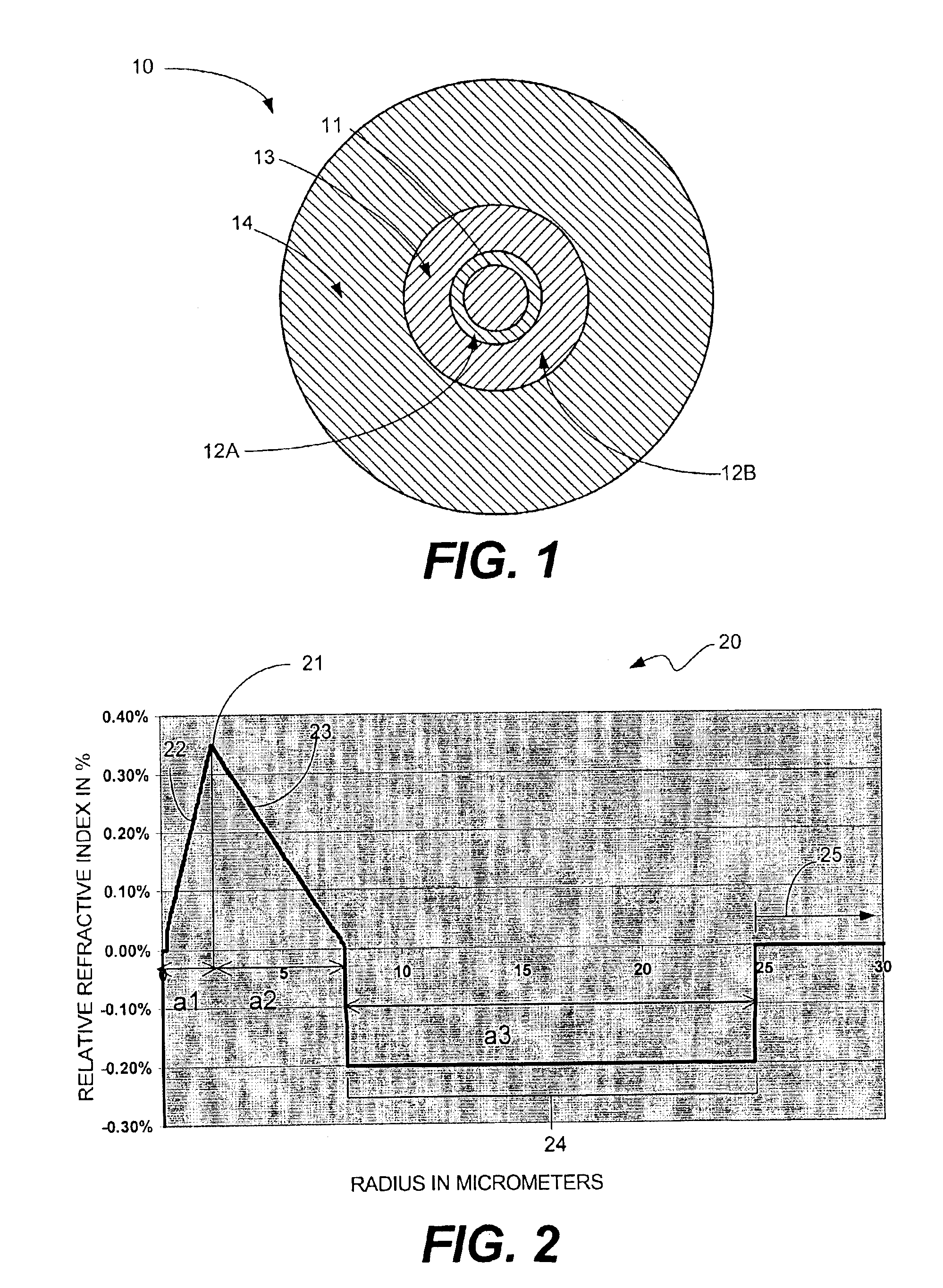
[0018]FIG. 1 is a cross-sectional end view of a super-large effective area (SLA) optical fiber 10 in accordance with an example embodiment of the present invention. The SLA fiber 10 includes a segmented central core region 11, a first annular region 13 that surrounds the core region 11 and an outer cladding 14 that surrounds the trench region. The core region 11 is segmented into first and second core-region portions, 12A and 12B, which have relative refractive index values n1a and n1b, respectively, which are different from each other. The first annular region, or trench region) 13 has a nominal refractive index n2. The outer cladding 14 has a nominal refractive index n3. As discussed below in detail with reference to FIG. 7, an SLA fiber in accordance with the present invention may have additional regions, such as another negative refractive index region in addition to the trench region 13.

[0019]It should be noted that the optical fiber 10 shown in FIG. 1 is not drawn to scale (th...


PUM


Abstract

A super-large-effective-area (SLA) optical fiber that is suitable for communicating over a wide wavelength range and that, because of its large effective area, suppresses nonlinear effects that typically result from interaction between signal channels. The effective area, Aeff, of the SLA fiber of the present invention preferably is equal to or greater than approximately 80 μm2 at a wavelength window around 1310 nm. The cutoff wavelength of the SLA fiber of the present invention preferably is less than 1310 nm. Thus, the SLA fiber of the present invention has a very large effective area and a very low cutoff wavelength. In accordance with the present invention, a variety of SLA fibers are provided that all have very large effective areas and desirable transmission properties. The large effective areas of the SLA fibers of the present invention enable nonlinear effects to be suppressed, as well as Stimulated Brillouin Scattering in analog transmission. The large effective areas also enable attenuation to be reduced. The result of suppressing nonlinear effects and reducing attenuation enable signals to be transmitted over long distances and over a broad bandwidth.

Description

BACKGROUND OF THE INVENTION[0001]1. Field of the Invention[0002]The invention relates to optical fibers. More particularly, the invention relates to a super-large-effective-area optical fiber that exhibits low loss and that has a broad operation wavelength range.[0003]2. Description of the Related Art[0004]Optical fibers are thin strands of glass or plastic capable of transmitting optical signals, containing relatively large amounts of information, over long distances and with relatively low attenuation. Typically, optical fibers are made by heating and drawing a portion of an optical preform comprising a refractive core region surrounded by a protective cladding region made of glass or other suitable material. Optical fibers drawn from the preform typically are protected further by one or more coatings applied to the cladding region.[0005]Advances in transmission over optical fibers have enabled optical fibers to have enormous bandwidth capabilities. Such bandwidth enables thousand...

Claims


Application Information

Patent Timeline
Patent Type & Authority Patents(United States)
IPC IPC(8): G02B6/036G02B6/02
CPCG02B6/02014G02B6/02019G02B6/03666G02B6/03611G02B6/03627G02B6/0365G02B6/0281G02B6/02266G02B6/0228
Inventor SUN, YIPECKHAM, DAVID W.WU, FENGQING
Owner FURAKAWA ELECTRIC NORTH AMERICA INC
Why Eureka
Try Eureka