Eureka AIR delivers breakthrough ideas for toughest innovation challenges, trusted by R&D personnel around the world.

Method for transmitting data over a data bus with minimized digital inter-symbol interference

a data bus and inter-symbol technology, applied in the direction of line-faulst/interference reduction, amplitude demodulation, pulse technique, etc., can solve the problem that the req data transmitted on other lines of the data bus during the first req pulse may not be sensed correctly by the data detection circuitry, and the data bus idles, etc. problem, to achieve the effect of minimizing the inter-symbol interference of digital control

Inactive Publication Date: 2005-06-07
SEAGATE TECH HDD HLDG +3
View PDF15 Cites 51 Cited by
  • Summary
  • Abstract
  • Description
  • Claims
  • Application Information

AI Technical Summary

Benefits of technology

[0011]Another object of the present invention is to transmit data over a data bus with minimized digital data inter-symbol interference.

Problems solved by technology

A problem can occur when the SCSI data bus idles with no data transfers for a prolonged period of time.
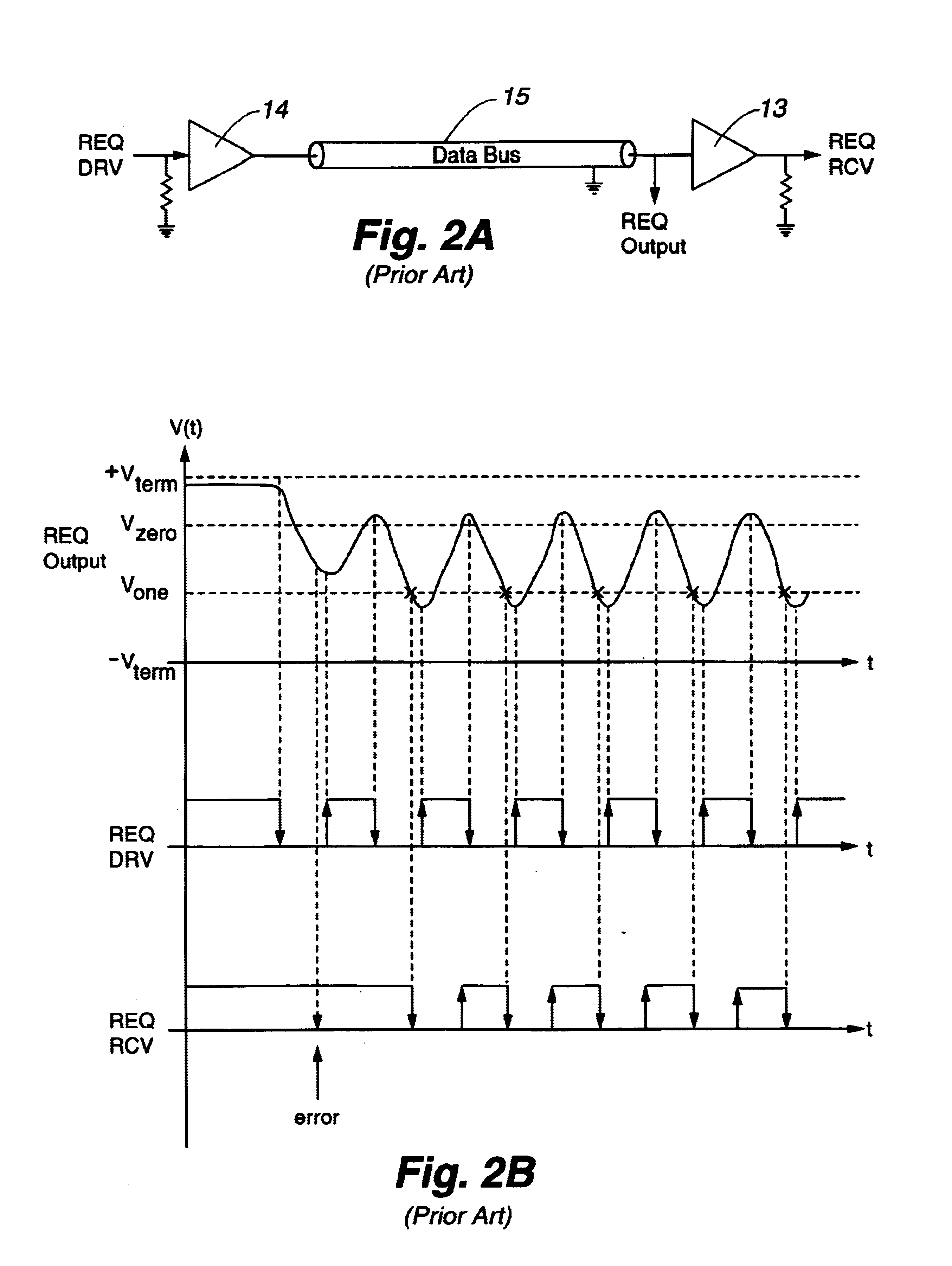
In one failure mode, there is insufficient time for the REQ signal to be sensed by the data detection circuitry during a first assertion of REQ before a subsequent REQ is asserted.
Consequently, REQ data transmitted on other lines of the data bus during the first REQ pulse may not be sensed correctly by the data detection circuitry and may be lost.
A second failure mode occurs when the REQ signal is not sensed at all by the data detection circuit within predetermined time constraints.
Referring to FIG. 3, a similar problem occurs when the user data signal is unchanged (all zeros or ones) for a prolonged period of time.
However, this period of time is often insufficient for the first data signal transition to be sensed by the data detection circuitry, thereby causing the data defined within this first large data signal transition to be lost.
However, an increase in data frequency causes a proportional decrease in the time period allowable for control and data pulses to be sensed by the data detection circuitry.

Method used


Image

  • Method for transmitting data over a data bus with minimized digital inter-symbol interference
  • Method for transmitting data over a data bus with minimized digital inter-symbol interference
  • Method for transmitting data over a data bus with minimized digital inter-symbol interference

Examples


Embodiment Construction

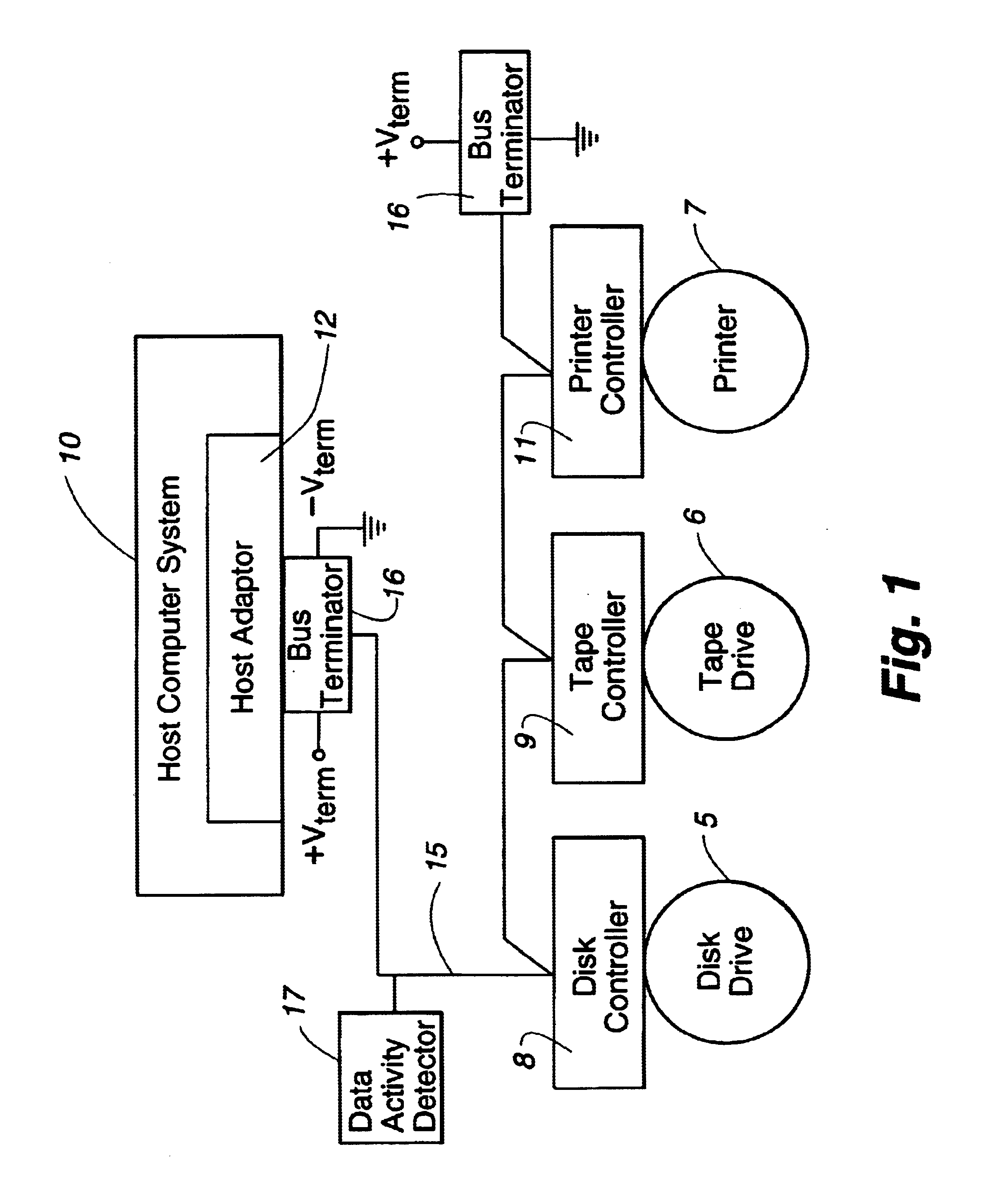
[0024]Referring again to FIG. 1, generally, the present invention comprises a method for bi-directionally transmitting data from a sender to a receiver via a data bus 15. In one instance, the sender is defined as a host computer system 10 and the receiver is defined as a peripheral device such as the disk drive 5 for transmitting data from the host computer system 10 to the disk drive 5. Alternatively, the sender is defined as a peripheral device such as the disk drive 5 and the receiver is defined as the host computer system 10 for transmitting data from the disk drive 5 to the host computer system 10.

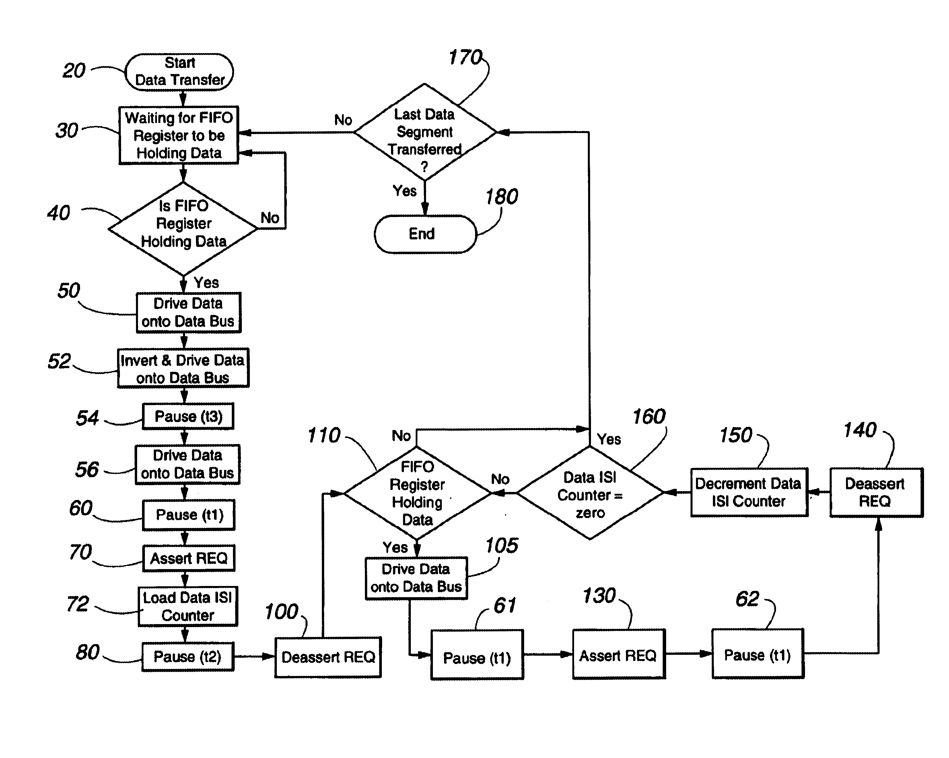
[0025]One preferred embodiment of the present invention as set forth herein is a method for transmitting data from the disk drive 5 to the host computer system 10 via the data bus 15, such as a SCSI data bus, with minimized digital inter-symbol interference. Referring to FIG. 4, the method comprises the steps of executing a start data transfer command at step 20 from the disk drive 5 ...


PUM


Abstract

A method for transmitting data over a data bus with minimized digital control and data inter-symbol interference. The voltage level on the data bus is not permitted to reach the quiescent negated voltage level set by the bus terminator voltage. Additional time is provided for data detection circuitry to detect a first segment of data transferred over the data bus. A pause time is enabled after the data bus has been idle or paused for a prolonged period. After the first segment of data has been transferred, the method returns to normal operation by pausing for a normal period of time for data detection circuitry to detect subsequent segments of data transferred over the data bus. Additionally, during prolonged synchronous data transfers with unchanged data bits, the data bus is inverted and driven for further regulating the data bus voltage.

Description

CROSS-REFERENCE TO RELATED APPLICATIONS[0001]This application is a continuation of U.S. application Ser. No. 09 / 220,089, filed Dec. 23, 1998 now U.S. Pat. No. 6,577,687.FIELD OF THE INVENTION[0002]The invention relates generally to transmitting binary data over a data transmission line and more precisely to transmitting binary data over a data transmission line with minimized digital inter-symbol interference.BACKGROUND OF THE INVENTION[0003]As illustrated in FIG. 1, data is typically transmitted back and forth between a host computer system 10 and peripheral devices, such as disk drive 5, tape drive 6, or printer 7, over a data bus 15. The data bus 15 couples the host computer system 10 and the peripheral devices together and enables the exchange of data between the system and the devices. One type of data bus is a Small Computer System Interconnect (SCSI) data bus. A SCSI data bus can be configured in different ways and has several modes of operation. One configuration and mode of...

Claims


Application Information

Patent Timeline
Patent Type & Authority Patents(United States)
IPC IPC(8): G06F13/40H04L29/08
CPCG06F13/4072
Inventor HALL, DANALESHAY, BRUCE
Owner SEAGATE TECH HDD HLDG
Why Eureka
Eureka Blog
Learn More