
Hardware efficient digital control loop architecture for a power converter

a digital control loop and power converter technology, applied in the direction of code conversion, conversion with intermediate conversion to dc, instruments, etc., can solve the problems of not being able to route high-current signals through the system, new and significant problems in power supply delivery,

Active Publication Date: 2007-07-03
INTERSIL INC
View PDF9 Cites 85 Cited by
  • Summary
  • Abstract
  • Description
  • Claims
  • Application Information

AI Technical Summary

Benefits of technology

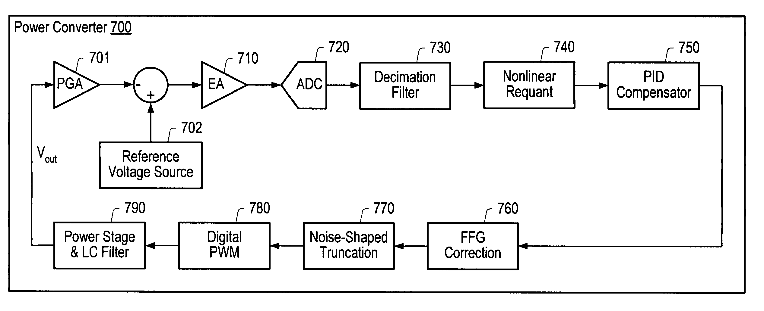
[0030]The power converter includes a digital filter for calculating the average of the digitized error signal. The power converter may also include a nonlinear requantizer for reducing the number of codes corresponding to the output of the digital filter to values that are spaced at non-uniform intervals away from a center code. In one embodiment, the nonlinear requantizer may reduce the number of codes corresponding to the output of the digital filter to values that are represented as a sum of a reduced number of powers of 2. In another embodiment, the nonlinear requantizer may reduce the number of codes to values that are spaced at increasing powers of 2 away from the center code.

Problems solved by technology

This rapid evolution has created new and significant problems in delivery of the power to and removal of waste heat from these ICs.
Power supply design is now a much more critical and difficult task than it was a few years ago.
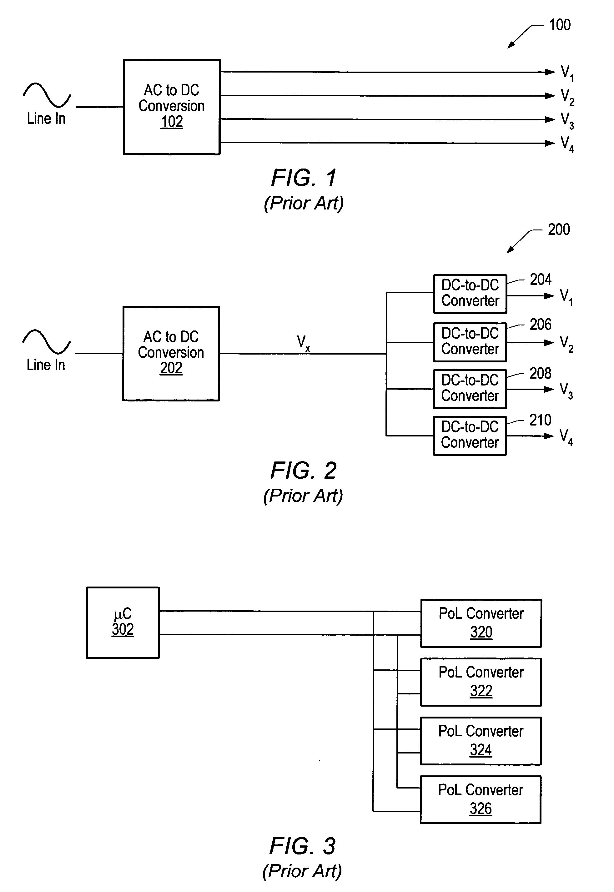
However, it may not be practical to route high-current signals throughout a system.
In many power distribution systems it is typically not enough to just distribute power around a system to the various POLs.
Dense electronic systems often generate excessive waste heat.
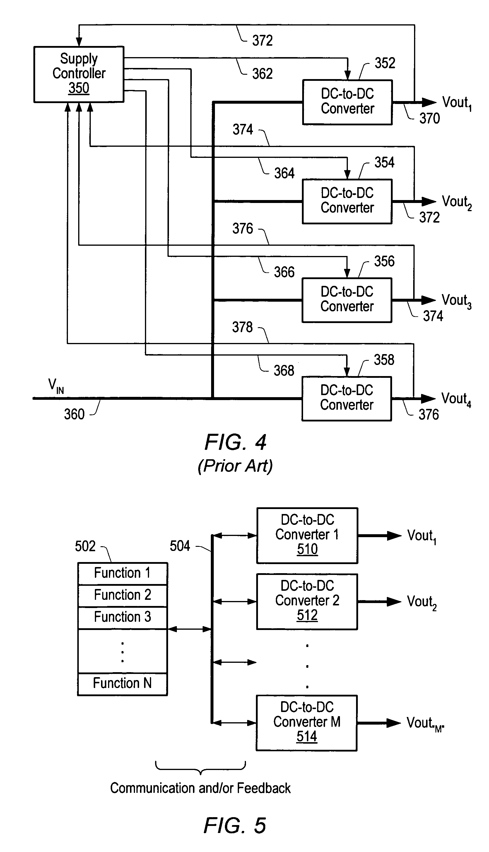
Routing of such signals is often difficult, while no true communication is established between various POL converters and / or between the POL converters and any other elements of the system.
In general, microcontroller 302 checks status for one POL converter at a time, which may be viewed as a disadvantage when more interactive, real-time communication is desired in a system.
In practice, designs such as this may consume a substantial amount of power and require a significant amount of die area, which may adversely impact power converter efficiency and manufacturing cost effectiveness.

Method used


Image

  • Hardware efficient digital control loop architecture for a power converter
  • Hardware efficient digital control loop architecture for a power converter
  • Hardware efficient digital control loop architecture for a power converter

Examples


Embodiment Construction

[0050]The following references are hereby incorporated by reference in their entirety as though fully and completely set forth herein:

[0051]U.S. Patent Application Publication No. 2004 / 0201279 (Ser. No. 10 / 820,976), titled “Method And Apparatus For Improved DC Power Delivery, Management And Configuration,” filed Jun. 21, 2004.

[0052]U.S. patent application Ser. No. 11 / 198,698, titled “Method For Using a Multi-Master Multi-Slave Bus For Power Management,” filed Aug. 5, 2005.

Power Distribution System

[0053]FIG. 5 is a block diagram of one embodiment of a power distribution system. As shown, the common functions required in a complex DC power system may be combined in a single controller rather than treated as separate IC functions. As illustrated in the embodiment of FIG. 5, a controller 502 managing functions 1 through N may be coupled to DC-to-DC converters 1 through M (illustrated by example as power converters 510, 512 and 514) via a digital bus 504. Digital bus 504 may be a serial ...


PUM


Abstract

A power converter including a hardware efficient control loop architecture. Error detection circuitry may generate an error signal based on the difference between a power converter output voltage and a reference voltage. An oversampling ADC may digitize the error signal. The transfer function associated with the ADC may include quantization levels spaced at non-uniform intervals away from a center code. A digital filter may calculate the average of the digitized error signal. A nonlinear requantizer may reduce the number of codes corresponding to the output of the digital filter. A proportional integral derivative (PID) unit may multiply the output of the nonlinear requantizer by PID coefficients to generate a PID duty cycle command, and a gain compensation unit may dynamically adjust the PID coefficients to maintain a constant control loop gain. A noise-shaped truncation unit including a multi-level error-feedback delta sigma modulator may reduce the resolution of the PID duty cycle command.

Description

PRIORITY CLAIM[0001]This application claims benefit of priority of U.S. provisional application Ser. No. 60 / 723,282 titled “System and Method for Implementing Distributed Power Management”, filed Oct. 3, 2005.BACKGROUND OF THE INVENTION[0002]1. Field of the Invention[0003]This invention relates to power converters and, more particularly, to digital control loop architecture.[0004]2. Description of the Related Art[0005]From 1995 to 2001, the highest density processors from manufacturers such as Intel went from a power consumption rate of about 30 Watts at 3.3 V to a power consumption rate of about 90 Watts delivered at 1.5 V. A simple application of the power-voltage-current relationship reveals that the total current consumed by these chips has increased from nine amps to about 60 amps in a very short time period. There are similar analogies with all larger digital integrated circuits (ICs).[0006]This rapid evolution has created new and significant problems in delivery of the power ...

Claims


Application Information

Patent Timeline
IPC IPC(8): H03M1/88H03M1/12
CPCH02M3/157
Inventor ALEXANDER, MARK A.HEINEMAN, DOUGLAS E.FERNALD, KENNETH W.HERRINGTON, SCOTT K.
Owner INTERSIL INC
Learn More