
Method and circuit for setup and hold detect pass-fail test mode

a technology of detection mode and test mode, applied in the field of on-chip test circuits, can solve the problems of suah test performance, test result failure at 1.5 ns, difficulty in deciding character, etc., and achieve the effect of reducing the overhead burden of testing resources, low time, resource and monetary cost, and short test duration

Inactive Publication Date: 2005-06-07
INFINEON TECH LLC
View PDF19 Cites 3 Cited by
  • Summary
  • Abstract
  • Description
  • Claims
  • Application Information

AI Technical Summary

Benefits of technology

[0010]The present invention provides a method and circuit thereof for performing setup and hold (SUAH) testing with a reduced number of requisite test vectors. The present invention also provides a method and circuit for performing SUAH testing on memory systems and other ICs without having to write back into the memory, by directly testing the input latch stage. The present invention further provides a method and system for performing SUAH testing at the register stage, which does not require gross involvement of other IC stages. Further still, the present invention provides a method and system for SUAH testing with a relatively small overhead burden on testing resources and low time, resource, and monetary cost.
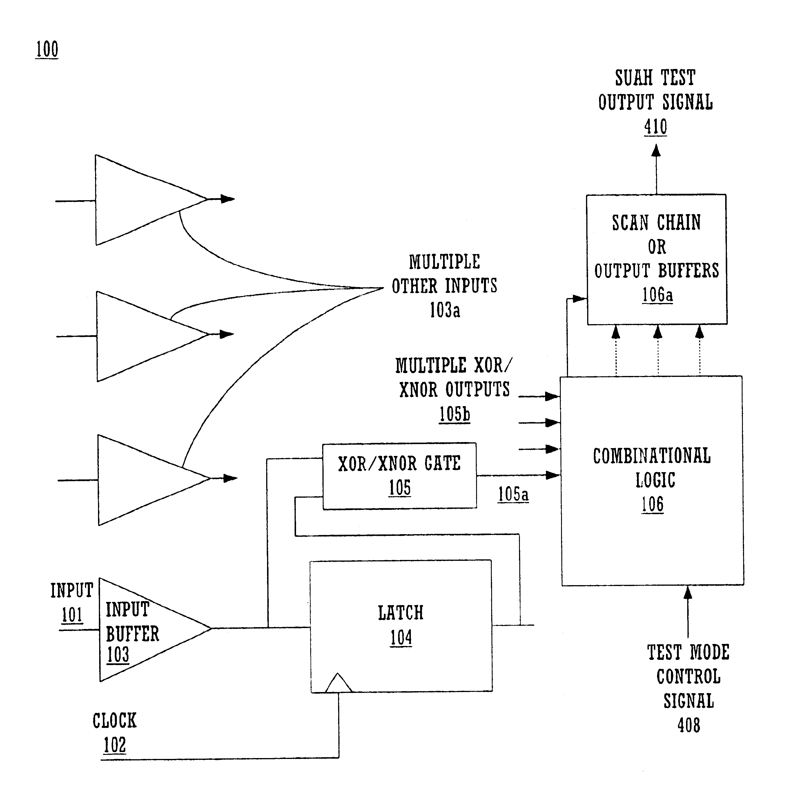
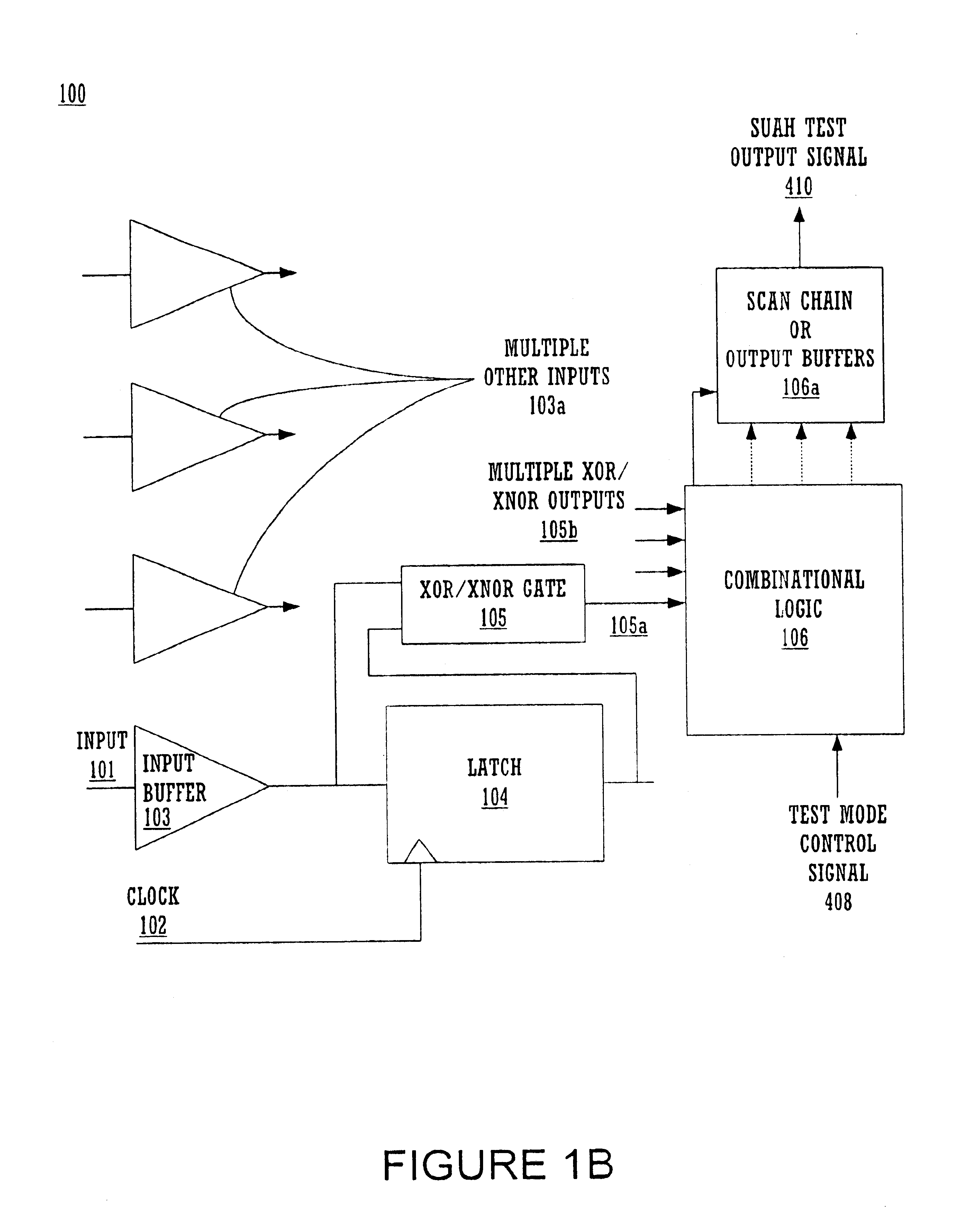
[0012]In another embodiment, the present invention also provides a method and circuit for performing SUAH testing on memory systems without having to write back to the memory by direct testing of the latches of the input stage. The method and circuit thus embodied enables SUAH testing free of the constraints of any of the particular data, controls, and addresses of the device. Thus, even in pipelined / complex SRAM and ASIC components with cascaded registers / latches, this embodiment of the present invention averts the need for multiple clock cycles, which would otherwise be required for sequentially writing data to each and every one of their addresses, and then reading the data back from these addresses to test to detect a test pass or a failure result.
[0014]In yet another embodiment still, the present invention provides a method and system for SUAH testing which places a relatively small overhead burden on testing resources and low time, resource, and monetary cost. Further, the advantages and benefits to test brevity and simplicity contributed jointly, severally, or individually by the foregoing embodiments may combine to augment the advantage conferred by the present embodiment. For example, by using only two single clock cycles to perform the SUAH test in one embodiment, the test duration is accordingly very short. More, multiple clock cycles are obviated by the embodiment dispensing with the write back and read / particular address requirement, accordingly also reducing the duration of the test. By requiring use of a small test vector array in one embodiment, the test is simplified. The individual effect of this embodiment, or the combined effects of some or all of the other embodiments with it, make the overall burden posed on the testing overhead quite small. This has the advantageous effect of making a SUAH test by the methods and circuits of any or all of the embodiments of the present invention relatively inexpensive, monetarily and otherwise.

Problems solved by technology

In testing this parameter, it has been sometimes difficult to decide the character of the result as pass or fail.
Conversely, if the circuit is non-functional at that timing value, the test result is a failure at 1.5 ns.
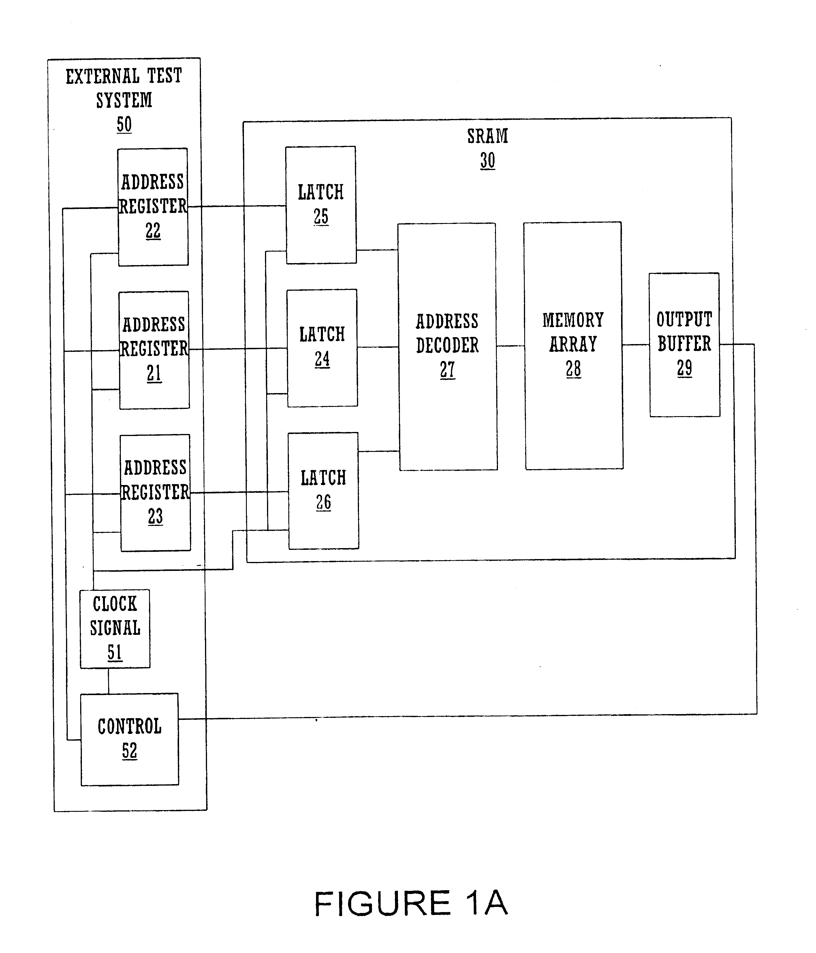
In the conventional art, a problem arises in the performance of SUAH tests on large scale and especially, very large scale ICs (LSI, VLSI) such as SRAM, in detecting whether or not a circuit passes or fails.
The passage of time involved in the multiple clock cycles required to accomplish these serial tasks further increases the time required to complete SUAH tests, and consequently increases costs involved.
This places a substantial overhead burden on testing resources, and is quite significant in terms of the cost of testing in time, resources, and expense.

Method used


Image

  • Method and circuit for setup and hold detect pass-fail test mode
  • Method and circuit for setup and hold detect pass-fail test mode
  • Method and circuit for setup and hold detect pass-fail test mode

Examples


Embodiment Construction

[0027]Reference will now be made in detail to the preferred embodiments of the invention, examples of which are illustrated in the accompanying drawings. While the invention will be described in conjunction with the preferred embodiments, it will be understood that they are not intended to limit the invention to these embodiments. On the contrary, the invention is intended to cover alternatives, modifications and equivalents, which may be included within the spirit and scope of the invention as defined by the appended claims. Furthermore, in the following detailed description of the present invention, numerous specific details are set forth in order to provide a thorough understanding of the present invention. However, it will be obvious to one of ordinary skill in the art that the present invention may be practiced without these specific details. In other instances, well-known methods, procedures, components, and circuits have not been described in detail so as not to unnecessarily...


PUM


Abstract

A method and circuit thereof for performing setup and hold (SUAH) testing on integrated circuits including, but not limited to SRAM, utilizing a relatively low number of test vectors, obviating the conventional requirement of writing to and reading back from each and every memory address. In one embodiment, a first test data signal of all zeros (0) is inputted to the input stage of the SRAM under test, and a subsequent second data signal of all ones (1) follows. In one embodiment, XOR / XNOR gates detect differences in data signals between the inputs and outputs of input stage latches / registers after clocking. In one embodiment, detected differences are combined into an error signal in combinational logic. In one embodiment, error signals are exported serially to a test system by a scan chain. Alternatively, in another embodiment, error signals are exported in parallel via individual output drivers.

Description

BACKGROUND OF THE INVENTION[0001]1. Field of the Invention[0002]The present invention relates to the field of on-chip test circuits. Specifically, the invention is designed to perform a set-up and hold (SUAH) test function.[0003]2. Related Art[0004]In the manufacture of silicon and other microelectronic devices, such as integrated circuits (IC), various testing functions are performed including the active testing of wafers and dies in which the ICs are embedded prior to their isolation. One such test, especially important in testing the functionality of synchronous static random access memories (SRAM) and application specific integrated circuits (ASIC), is the setup and hold (SUAH) test. SUAH testing determines whether SRAM, ASIC, or other integrated circuit designs meet crucial synchronous timing parameter specifications. Setup refers to the time in which a data signal has to be at a certain circuit locus prior to a clock transition signal. Hold refers to the duration of time for w...

Claims


Application Information

Patent Timeline
IPC IPC(8): G11C29/00G11C29/40
CPCG11C29/40G11C29/1201G11C11/41G11C2029/3202
Inventor DAVIDSON, COLIN
Owner INFINEON TECH LLC
Learn More