Unitized seal for a gas spring

a gas spring and unitized seal technology, applied in the field of gas springs, can solve the problems of increasing slowing the overall production of sealing arrangement, and a large number of parts comprising the sealing arrangement, so as to reduce the permeability of the pressurized gas, reduce the cost of sealing arrangement production, and improve the useful life of the gas spring.

Inactive Publication Date: 2005-06-14
TROSTEL
View PDF47 Cites 7 Cited by
  • Summary
  • Abstract
  • Description
  • Claims
  • Application Information

AI Technical Summary

Benefits of technology

[0016]It is still another object of the invention to provide a gas spring seal assembly that has a reduced permeability to the pressurized gas within the gas spring to extend the useful life of a gas spring cylinder in which the gas spring seal assembly is utilized.
[0017]It is still a further object of the invention to provide a gas spring seal assembly in which the unitized seal can be quickly and inexpensively formed using a single stage manufacturing process.
[0018]The present invention is an improved gas spring seal assembly that functions similarly to the prior art seals and utilizes a unitized part which incorporates various parts of prior art seals into a single seal. The unitized seal includes a substantially rigid insert molded integrally within an outer resilient sealing layer. In one form, the insert may be made of a thermoplastic material and the resilient sealing layer may be made of an elastomeric material. The thermoplastic insert and elastomeric sealing layer can be unitarily formed in a single stage operation in which the elastomeric layer is molded about the insert. The insert and elastomeric layer are securely bonded to one another during this process due to the reactivity of the curing elastomer, negating the need for any adhesive to be applied to the exterior of the insert. Further, the bonding between the insert and the elastomeric layer is enhanced by the covulcanization of the insert 5 and the elastomeric layer.
[0019]The thermoplastic insert in the unitized seal abuts the open end of the cylinder to properly position the seal. The insert defines a central opening that abuts and slidably engages the exterior surface of the rod, to axially align the rod with the open end of the gas spring cylinder and to guide movement of the rod relative to the cylinder. The insert, being formed of a rigid material, also serves to provide rigidity to the seal assembly and has a reduced permeability to the pressurized gas within the cylinder.
[0020]The elastomeric layer generally surrounds the exterior of the insert and sealingly engages the interior surface of the gas spring cylinder to retain the pressurized gas within the cylinder. The portion of the elastomeric layer disposed opposite the open end of the cylinder includes an opening aligned with the opening in the insert. The rod extends through the opening, and the elastomeric material sealingly engages the rod at the opening to prevent the rod lubricant and pressurized gas from passing through the seal assembly. With this construction, the rod guide and the first fluid seal of the prior art construction are combined into a single, unitized seal assembly which reduces manufacturing and assembly costs yet which effectively performs the functions of such components.
[0021]The seal assembly can also includes a reservoir seal abutting the unitized seal opposite the open end. The reservoir seal is constructed similarly to the second fluid seal of the prior art construction. The reservoir seal includes a circular opening positioned opposite the unitized seal and aligned with the openings in the seal through which the rod extends into the interior of the gas spring cylinder. The reservoir seal further defines a central interior space that holds the lubricant that coats the exterior surface of the rod and facilitates the sliding movement of the rod with respect to the seal assembly.

Problems solved by technology

While providing a reliable sealing arrangement for the gas spring, this prior art sealing arrangement has certain drawbacks.
First, the multitude of parts comprising the sealing arrangement requires a slow and complex process in order to properly assemble the sealing arrangement.
This process greatly increases the cost of production of the sealing arrangement and slows the overall production of the sealing arrangements.
Finally, the structure of the prior art sealing arrangement may allow a certain amount of the pressurized gas held within the cylinder to permeate through the sealing arrangement and escape from the cylinder, which adversely effects the ability of the gas spring to function in the desired manner.

Method used


Image

  • Unitized seal for a gas spring
  • Unitized seal for a gas spring
  • Unitized seal for a gas spring

Examples


Embodiment Construction

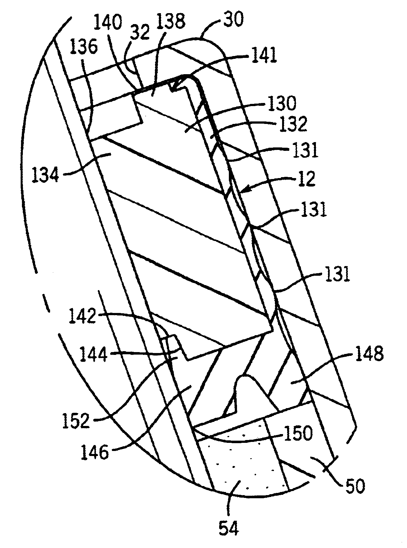
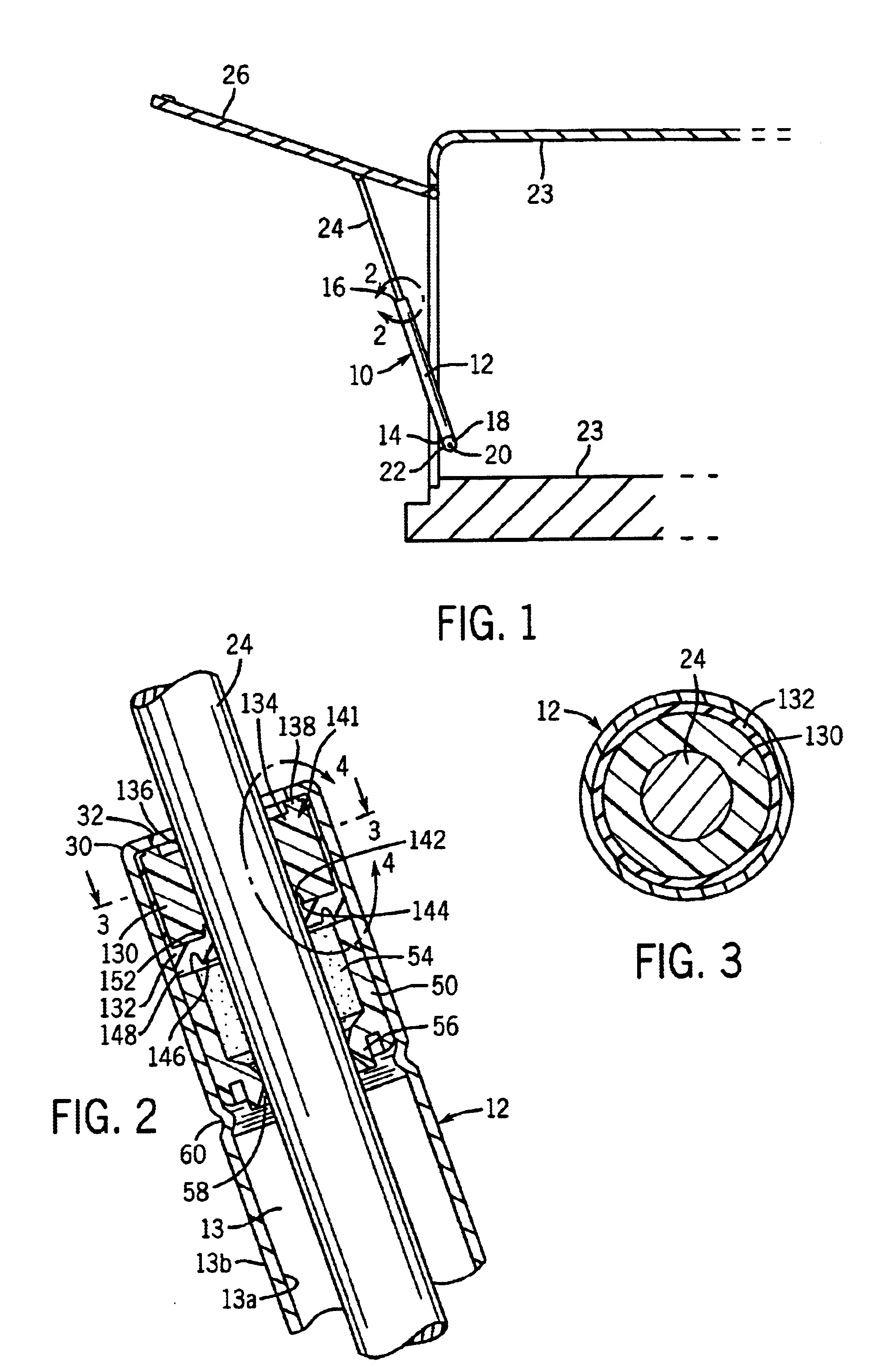
[0029]With reference now to the drawings in which like reference numerals designate like parts throughout the disclosure, FIG. 1 illustrates a gas spring indicated generally at 10 constructed according to the invention. Referring to FIGS. 1 and 2, gas spring 10 includes a body 12, such as a cylinder or pressure tube, having a piston cavity 13 defined by an inner surface 13a, in a manner as is known. Tube 12 further defines an outer surface 13b, a closed end 14 and an open end 16. The closed end 14 includes an outwardly extending flange 18 that includes a hole 20 that is adapted to receive a screw 22 or other fastening device to pivotally secure the closed end 14 of the tube 12 to a structure 23. The spring 10 also includes a rod 24 slidably engaged with the tube 12 through the open end 16 and pivotally secured opposite the tube 12 to a door 26 that is hingedly connected to the structure 23. The open end 16 is formed by an inwardly curving end wall 30 of tube 12 that defines a rim 31...


PUM


Abstract

A unitized seal for use in a gas spring seal assembly. The unitized seal includes a rigid thermoplastic insert having an elastomeric sealing layer surrounding the insert and bonded to the insert. The insert provides rigidity to the seal and includes a central, axial opening that receives and guides a rod slidably engaged with the insert. The sealing layer engages the interior surface of the gas spring cylinder to prevent the pressurized gas contained within the gas spring from escaping around the seal. The sealing layer also includes a central, axial opening aligned with the passage in the insert that slidably engages the rod and further prevent gas from escaping the gas spring cylinder. The unitized seal may be formed in a single or two-step process. In the single step process, the insert and sealing layer are formed by injection molding processes in a single mold and are bonded to one another by a subsequent covulcanization process. In the two-step process, the insert is formed in a first injection molding step, and has an adhesion promoter applied to the exterior of the insert. The coated insert is then placed within a second mold that is used to form the sealing layer about the insert in a subsequent injection molding process. The adhesion promoter intimately bonds the sealing layer to the insert forming the unitized seal.

Description

CROSS REFERENCES TO RELATED APPLICATIONS[0001]This application claims priority to U.S. Provisional Patent Application No. 60 / 312,480 filed on Aug. 15, 2001.STATEMENT REGARDING FEDERALLY SPONSORED RESEARCH[0002]Not Applicable.FIELD OF THE INVENTION[0003]The present invention relates to gas springs and more specifically to a unitized seal for a seal assembly used in containing the gas and lubricating fluid within the gas spring.BACKGROUND OF THE INVENTION[0004]Gas springs are used in a variety of applications to selectively position a movable member with respect to a static member. The gas spring is formed from a hollow cylinder having an open end and a closed end. The closed end is typically attached to the static member, such as through a pivotable mounting arrangement, so as to provide a stable base for the gas spring. The open end of the cylinder defines a circular opening that is adapted to receive an elongated rod, which includes an outer end adapted for connection to the movabl...

Claims


Application Information

Patent Timeline
Patent Type & Authority Patents(United States)
IPC IPC(8): F16F9/36F16J15/32F16F9/00F16F9/32F16J15/18
CPCF16F9/362F16F9/3278
Inventor ZAFAR, MUHAMMAD SALIM
Owner TROSTEL
Why Eureka
Try Eureka