
Backlight system with multilayer optical film reflector

a backlight system and optical film technology, applied in non-linear optics, synthetic resin layered products, domestic applications, etc., can solve the problems of degrading the performance of the backlight, increasing the absorption loss, and reducing the efficiency of the backlight. , to achieve the effect of reducing the cost, weight and bulk of the backlight system, high light efficiency and low weigh

Inactive Publication Date: 2005-06-14
3M INNOVATIVE PROPERTIES CO
View PDF174 Cites 154 Cited by
  • Summary
  • Abstract
  • Description
  • Claims
  • Application Information

AI Technical Summary

Benefits of technology

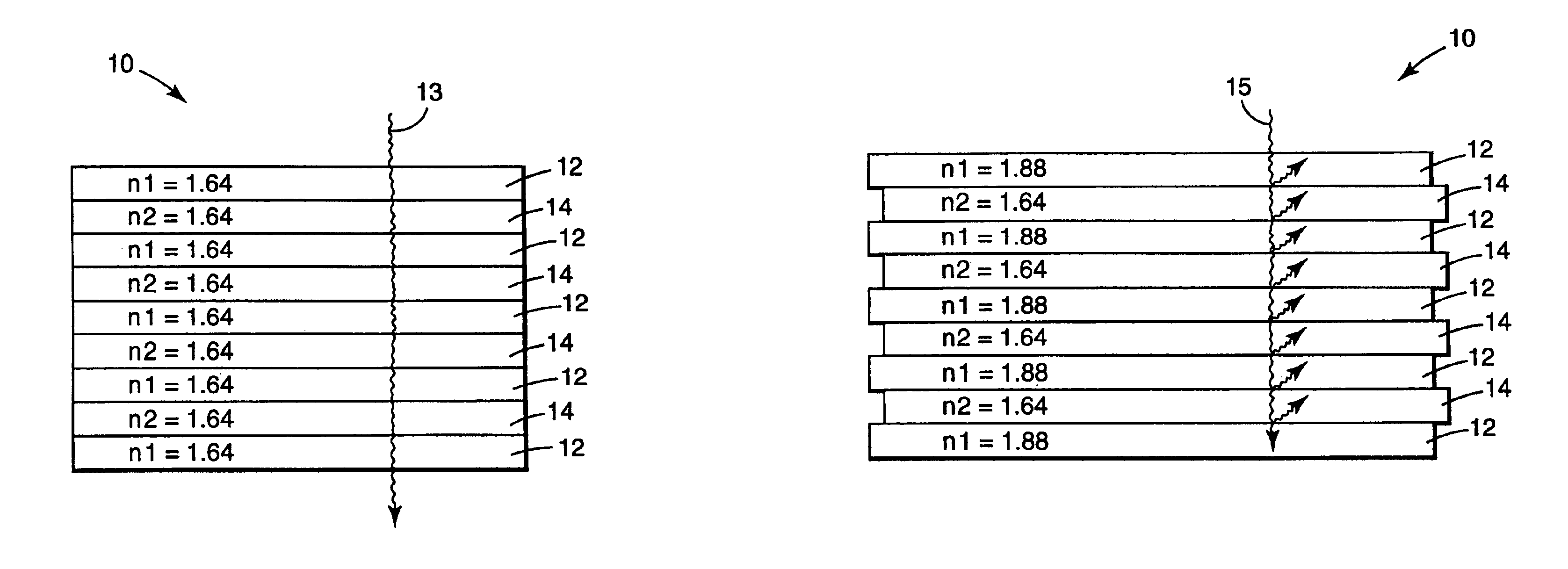
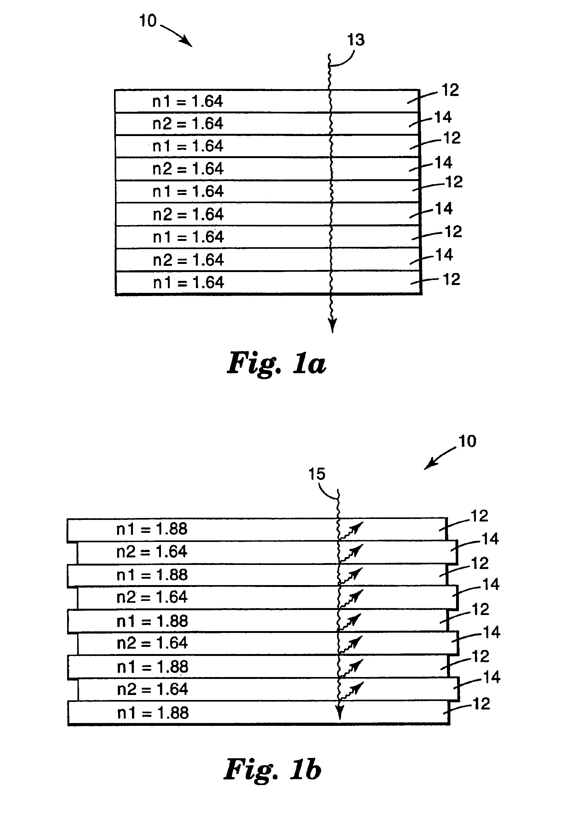
[0013]Providing the multilayer optical film for lamp cavity mirrors and / or back reflectors in backlight systems according to the present invention provides a number of advantages. One advantage is the low absorptivity of the film. The multilayer optical film according to the present invention can reflect over 99% of the light striking the surface of the film.
[0014]Another advantage is that the multilayer optical film is also highly efficient at reflecting light whether it is incident normal to the film surface or off-axis.
[0015]Yet another advantage of backlight systems employing multilayer optical film reflectors is that the multilayer optical film is relatively low in weight as compared to many conventional reflectors.
[0016]Still another advantage of backlight systems employing multilayer optical film back reflectors is that because the film is relatively thin as compared to many conventional reflectors, the backlight systems can be thinner than a backlight system employing a convention back reflector.
[0017]Still a further advantage is that an entire light guide can be constructed using multilayer optical film according to the present invention for both the front and back surfaces of the light guide, thereby eliminating the need for a separate light guide and further reducing the cost, weight and bulk of backlight systems.
[0018]Backlight systems according to the present invention can also incorporate recycling technologies, such as structured films and / or reflective polarizers, without incurring the significant absorptive losses associated with conventional reflectors.

Problems solved by technology

A primary disadvantage with the conventional reflectors used in the lamp cavity and at the back surface of the light guide is, however, their relatively high absorptivities and high transmission of incident light.
The absorbed light is, of course, not available to the viewer, thereby degrading performance of the backlight.
The absorptive losses are, of course, increased with every reflection of light from the surface of conventional reflectors.
These absorptive losses are also substantially increased when the backlight is used in combination with various light recycling films such as a structured partially reflective film.
Although recycling light in that manner is generally desired, it is a disadvantage when combined with conventional reflectors because a portion of the light which is reflected back into the light guide is absorbed or transmitted by the conventional back reflectors.
Those increased absorption losses reduce the luminance or brightness attainable by this combination of the backlight system.

Method used


Image

  • Backlight system with multilayer optical film reflector
  • Backlight system with multilayer optical film reflector
  • Backlight system with multilayer optical film reflector

Examples


example 1 (

PEN:THV 500, 449, Mirror)

[0060]A coextruded film containing 449 layers was made by extruding the cast web in one operation and later orienting the film in a laboratory film-stretching apparatus. A Polyethylene naphthalate (PEN) with an Intrinsic Viscosity of 0.53 dl / g (60 wt. % phenol / 40 wt. % dichlorobenzene) was delivered by one extruder at a rate of 56 pounds per hour and THV 500 (a fluoropolymer available from Minnesota Mining and Manufacturing Company) was delivered by another extruder at a rate of 11 pounds per hour. The PEN was on the skin layers and 50% of the PEN was present in the two skin layers. The feedblock method was used to generate 57 layers which was passed through three multipliers producing an extrudate of 449 layers. The cast web was 20 mils thick and 12 inches wide. The web was later biaxially oriented using a laboratory stretching device that uses a pantograph to grip a square section of film and simultaneously stretch it in both directions at a uniform rate. ...

example 2 (

PEN:PMMA, 601, Mirror)

[0062]A coextruded film containing 601 layers was made on a sequential flat-film-making line via a coextrusion process. Polyethylene Naphthalate (PEN) with an Intrinsic Viscosity of 0.57 dl / g (60 wt. % phenol / 40 wt. % dichlorobenzene) was delivered by extruder A at a rate of 114 pounds per hour with 64 pounds per hour going to the feedblock and the rest going to skin layers described below. PMMA (CP-82 from ICI of Americas) was delivered by extruder B at a rate of 61 pounds per hour with all of it going to the feedblock. PEN was on the skin layers of the feedblock. The feedblock method was used to generate 151 layers using the feedblock such as those described in U.S. Pat. No. 3,801,429, after the feedblock two symmetric skin layers were coextruded using extruder C metering about 30 pounds per hour of the same type of PEN delivered by extruder A. This extrudate passed through two multipliers producing an extrudate of about 601 layers. U.S. Pat. No. 3,565,985 de...

example 3 (

PEN:PCTG, 449, Polarizer)

[0064]A coextruded film containing 481 layers was made by extruding the cast web in one operation and later orienting the film in a laboratory film-stretching apparatus. The feedblock method was used with a 61 layer feedblock and three (2×) multipliers. Thick skin layers were added between the final multiplier and the die. Polyethylene naphthalate (PEN) with an intrinsic viscosity of 0.47 dl / g (60 wt. % phenol / 40 wt. % dichlorobenzene) was delivered to the feedblock by one extruder at a rate of 25.0 pounds per hour. Glycol modified polyethylene dimethyl cyclohexane terephthalate (PCTG 5445 from Eastman) was delivered by another extruder at a rate of 25.0 pounds per hour. Another stream of PEN from the above extruder was added as skin layers after the multipliers at a rate of 25.0 pounds per hour. The cast web was 0.007 inches thick and 12 inches wide. The web was layer uniaxially oriented using a laboratory stretching device that uses a pantograph to grip a ...


PUM

PropertyMeasurementUnit
Fractionaaaaaaaaaa
Fractionaaaaaaaaaa
Fractionaaaaaaaaaa

Abstract

The present invention includes a backlight system incorporating a back reflector and / or a lamp cavity reflector constructed of a multilayer optical film.

Description

[0001]This is a continuation of application Ser. No. 08 / 915,553 filed Aug. 7, 1997, now abandoned which is a continuation of Ser. No. 08 / 494,981, filed Jun. 26, 1995, now abandoned.TECHNICAL FIELD[0002]The present invention relates to the field of backlight systems. More particularly, the present invention relates to improved backlight systems with multilayer optical film reflectors.BACKGROUND OF THE INVENTION[0003]Liquid crystal (LC) displays are widely used for laptop computers, handheld calculators, digital watches, and similar devices in which information must be displayed to a viewer. In many applications, the displays incorporate a backlight to provide the light necessary to view the display when ambient light entering the display and reflected back out of the display is insufficient.[0004]Backlight systems typically incorporate a light source and a light guide to direct light from the source and uniformly spread it over the display. Traditionally, light guides have been provi...

Claims


Application Information

Patent Timeline
IPC IPC(8): B32B27/36F21V8/00G02B1/10G02F1/1335G02F1/13G02B6/00G02F1/13357
CPCB32B27/36G02B5/0841G02B5/305G02B5/3083G02B6/0055G02B6/0056G02B6/0065G02B6/0043G02B6/0051G02F2001/133545G02B6/0061G02F1/133536G02F1/13362G02B6/0053G02F1/133545B32B2551/00B32B27/08B32B2325/00B32B2327/12B32B2333/12B32B27/302B32B27/304B32B2367/00B32B2307/416
Inventor WORTMAN, DAVID L.COBB, JR., SANFORDCULL, BRIAN D.WEBER, MICHAEL F.OUDERKIRK, ANDREW J.
Owner 3M INNOVATIVE PROPERTIES CO
Learn More