Cylindrical magnetron target and spindle apparatus

a cylindrical magnetron and target technology, applied in the direction of electrolysis components, vacuum evaporation coatings, coatings, etc., can solve the problems of difficult unscrewing existing collar designs, affecting the service life of cylindrical magnetron targets, etc., to improve the connection between the magnetron target and the supporting spindle, simplify the manufacturing process of the attachment apparatus, and improve the speed and ease of removal

Inactive Publication Date: 2005-06-14
BUEHLER AG
View PDF5 Cites 6 Cited by
  • Summary
  • Abstract
  • Description
  • Claims
  • Application Information

AI Technical Summary

Benefits of technology

[0006]The present invention includes an apparatus for attaching a rotatable cylindrical magnetron target to a rotatable support spindle. Several design improvements have been incorporated into the attachment apparatus for improving the magnetron target-to-support spindle connection. The objectives in creating the improved attachment apparatus includes increasing the speed and ease of removing and installing cylindrical rotating targets onto a support spindle, and simplifying the attachment apparatus and its manufacture by reducing the number of required parts while maintaining the advantages of a single water-to-vacuum seal. The invention also provides the option of a flexible or a fixed connection between the target and the spindle. The advantage of a flexible coupling is to allow movement in order to eliminate forces otherwise transferred through the spindle to the bearings and seals. Easy access to the fasteners is provided for fast removal. The problematic target collar is eliminated. Spindle run-out is no longer significantly affected by imperfect parallelism of the target face relative to the spindle attachment. This invention allows rotation in either direction. The present invention is less time-consuming and less expensive to repair. A target can be removed from the spindle up to five times faster than current methods.

Problems solved by technology

However, there are some drawbacks to the currently known attachment devices affixing a rotatable cylindrical magnetron target to a support spindle.
It is difficult to unscrew existing collar designs because the parts have become exposed to the sputtering process, the intense heating, and the coating build-up over the parts.
Other problems arise when attempting to unscrew target collars by hammering with a spanner wrench to disengage the target.
Additional problems are created by spindle run-out when there is imperfect parallelism between the target face and the spindle it is attached to.
Cylindrical magnetron target repair and replacement can be a costly, time-consuming process in its large manufacturing plant environment.
Currently known attachment devices involve a costly, time-consuming repair process when removing the spindle from the target for significant reasons.
It can be very difficult to access and to adjust the four loosening screws that are used to produce proper O-ring compression in the restricted space on the back of the spindle between the target and the end block from which the spindle protrudes.
Secondly, problems are caused when unscrewing the collar from the end of the target by inserting a spanner nut wrench into the gap on the back of the spindle and into some holes in the collar.
This hammering action can damage drive parts inside the end block and other drive-train components of the ion sputtering magnetron.

Method used


Image

  • Cylindrical magnetron target and spindle apparatus
  • Cylindrical magnetron target and spindle apparatus
  • Cylindrical magnetron target and spindle apparatus

Examples


Embodiment Construction

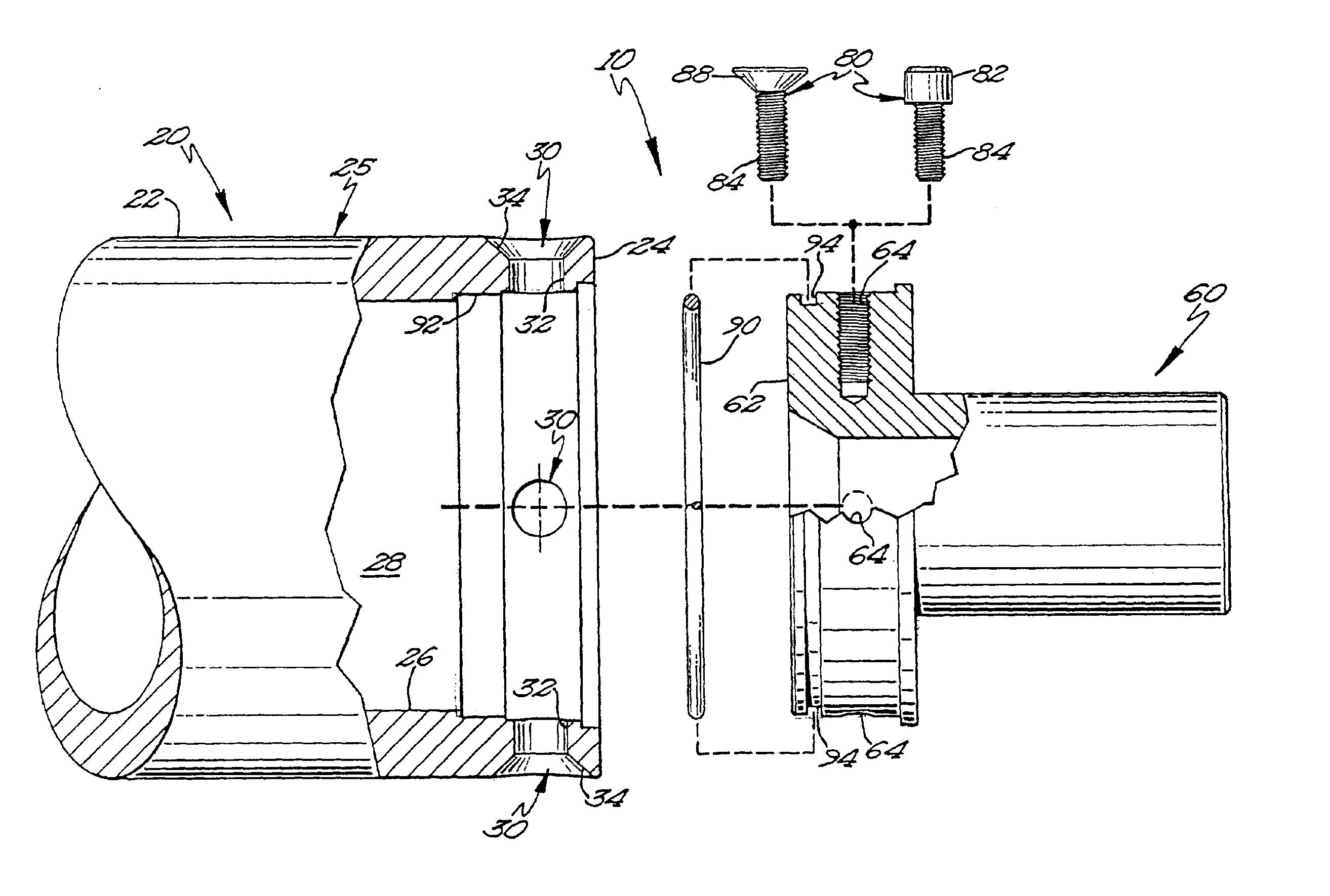
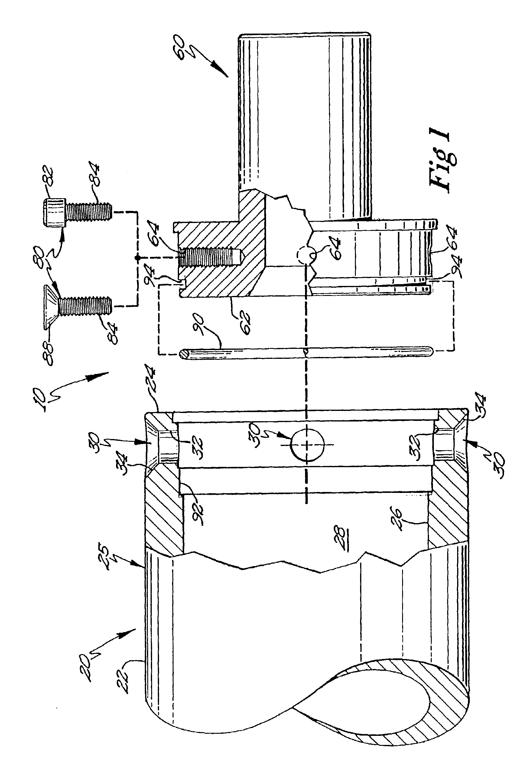
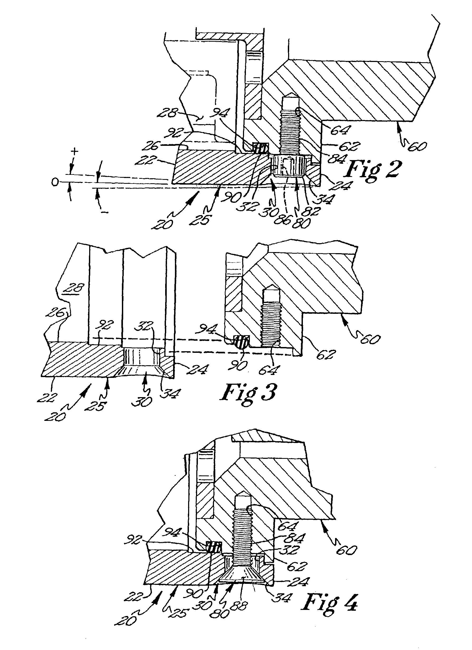
[0015]A preferred embodiment of the present invention is illustrated by way of example in FIGS. 1-4. With specific reference to FIG. 1, an improved cylindrical magnetron target and spindle attachment apparatus 10 includes a cylindrical target structure and a support spindle structure. The cylindrical target structure such as target 20 and the support spindle structure such as a spindle 60 are shown separated from each other but aligned for assembly into a single unit. The spindle 60, which is generally radially symmetrical about its axis, includes an extending portion of the support spindle structure such as a spindle plug 62 at the first end of the spindle 60. The spindle plug 62 has a thread aperture 64 defined at the circumference of the spindle plug 62 for receiving a thread 84 of a fastener such as a screw 80. A target 20 defines a receiver 25 in a hollow portion 28 of the target 20 interior 26. The spindle plug 62 is disposed within the receiver 25. An O-ring seal 90 is dispos...


PUM

PropertyMeasurementUnit
lengthaaaaaaaaaa
surface-areaaaaaaaaaaa
electrical poweraaaaaaaaaa

Abstract

A cylindrical magnetron target and spindle attachment apparatus for affixing a cylindrical magnetron target to a rotatable support spindle. The attachment apparatus includes a target and a spindle. The target defines a receiving portion. The spindle has a spindle plug. The spindle plug is disposed within the receiving portion of the target. The attachment apparatus increases the speed and ease of removing and installing cylindrical rotating targets onto a support spindle.

Description

BACKGROUND OF THE INVENTION[0001]The present invention relates generally to ion sputtering cylindrical magnetrons utilized for coating substrate articles and, more specifically, to attachment apparatuses for affixing a cylindrical magnetron target to a target mounting spindle.[0002]A major method for depositing a thin coating on large-surface-area substrates, such as computer monitor screens, architectural glass panels, automobile windshields, and the like is ion sputtering. The coating materials are deposited with a magnetron in a vacuum chamber upon the substrate utilizing reactive and / or inert gases and have been known in the art for some time. For example, a cylindrical target structure in a magnetron is described in Boozenny, et al., U.S. Pat. No. 5,096,562. The target structure employs a removable support spindle at each end of the cylindrical target structure. The support spindle at one end supplies and withdraws cooling fluid from within the cylinder that contains a driving ...

Claims


Application Information

Patent Timeline
Patent Type & Authority Patents(United States)
IPC IPC(8): H01J37/34H01J37/32
CPCH01J37/3423H01J37/3405
Inventor CROWLEY, DANIEL T.
Owner BUEHLER AG
Why Eureka
Try Eureka