

Transfer foil, transfer method, transfer apparatus, flat cathode-ray tube, and its manufacturing method
- Summary
- Abstract
- Description
- Claims
- Application Information
AI Technical Summary
Benefits of technology
Problems solved by technology
Method used
Image

Examples
Embodiment Construction
[0078]Referring now to the drawings, preferred embodiments of the invention are described in detail below.
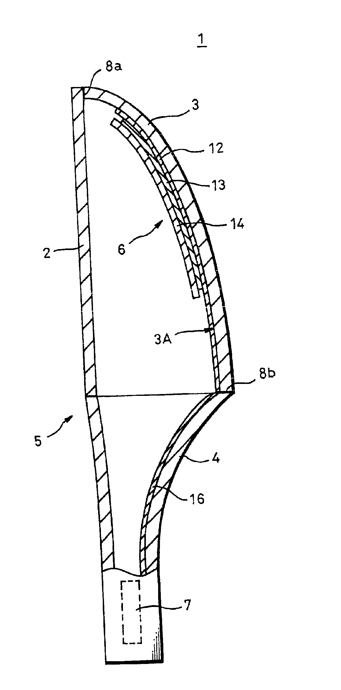
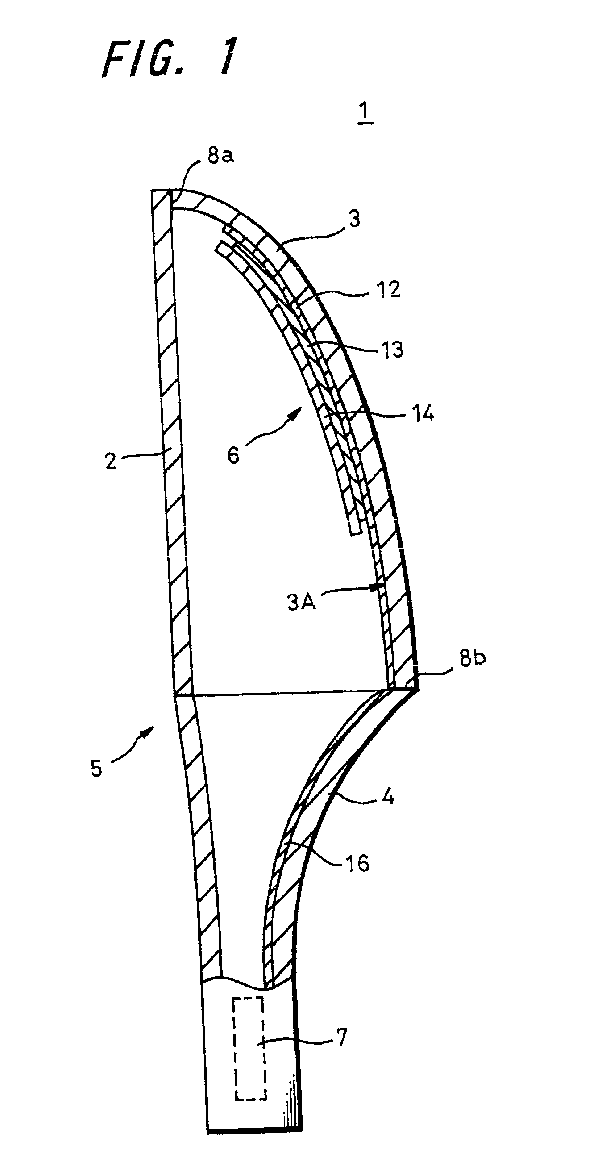
[0079]FIG. 1 and FIG. 2 show an embodiment of a flat cathode-ray tube of the invention. FIG. 1 is a structural diagram of a partial section, and FIG. 2 is a structural diagram of one panel seen by removing its front panel, or a screen panel in this example.
[0080]A flat cathode-ray tube 1 of the embodiment comprises a glass tube body 5 having a first panel, or a front panel 2 in this example, a second panel forming a fluorescent screen, or a screen panel 3 in the example, and a funnel 4 bonded together at frit glass junctions 8a, 8b, and an electron gun 7 sealed in the neck of the funnel 4. A deflection yoke, not shown, for deflecting the electron beam emitted from the electron gun 7 is disposed at the outside of the funnel 4.
[0081]The screen panel 3 is formed at a specified curvature in its inner side as shown in FIG. 2, and a riser, or so-called skirt 10 is formed at the edges ...
PUM
| Property | Measurement | Unit |
|---|---|---|
| Surface area | aaaaa | aaaaa |
Abstract
Description
Claims
Application Information