Cooling apparatus for integrated circuit

a technology of integrated circuits and cooling apparatuses, which is applied in the direction of emergency protective circuit arrangements, instruments, and the details of semiconductor/solid-state devices, etc., can solve the problems of increased power consumption, inability to operate the cooling fan, and easy burnout of the cpu

Inactive Publication Date: 2005-06-14
TWINHEAD INT
View PDF2 Cites 47 Cited by
  • Summary
  • Abstract
  • Description
  • Claims
  • Application Information

AI Technical Summary

Benefits of technology

[0008]Accordingly, the present invention provides a cooling apparatus which can control the speed of a fan so that an integrated circuit is sufficiently co...

Problems solved by technology

After the computer is restarted, the cooling fan does not operate since the loading of the CPU is not large enough.
The CPU is thus easily to burn out due to the high temperature.
Moreover, an output signal for the operation amplifier is continuously supplied to the cooling fan 14, thus, it causes an additional power consumption, especially in the application of notebook computer because a portable computer requires an additional battery to supply voltage to the CPU and the peripheries.
The design of the conventional fan cooling apparatus will increase power consumption and reduce the lifetime of the battery.
Furthermore, in case that the cooling fan is burned out, it can not be detected from the circuit design of the co...

Method used


Image

  • Cooling apparatus for integrated circuit
  • Cooling apparatus for integrated circuit
  • Cooling apparatus for integrated circuit

Examples


Embodiment Construction

[0024]Reference will now be made in detail to the present preferred embodiments of the invention, examples of which are illustrated in the accompanying drawings. Wherever possible, the same reference numbers are used in the drawings and the description to refer to the same or like parts.

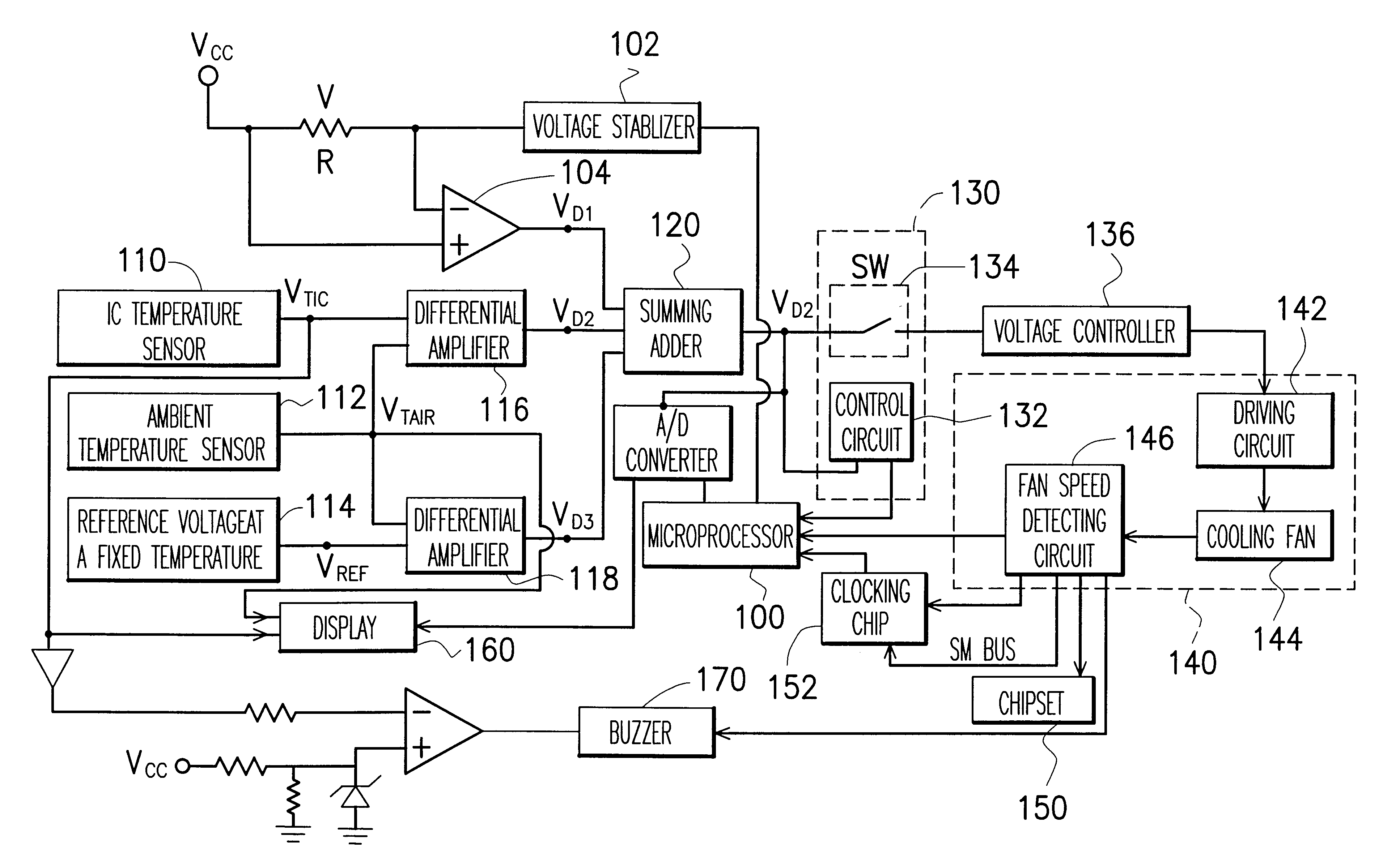
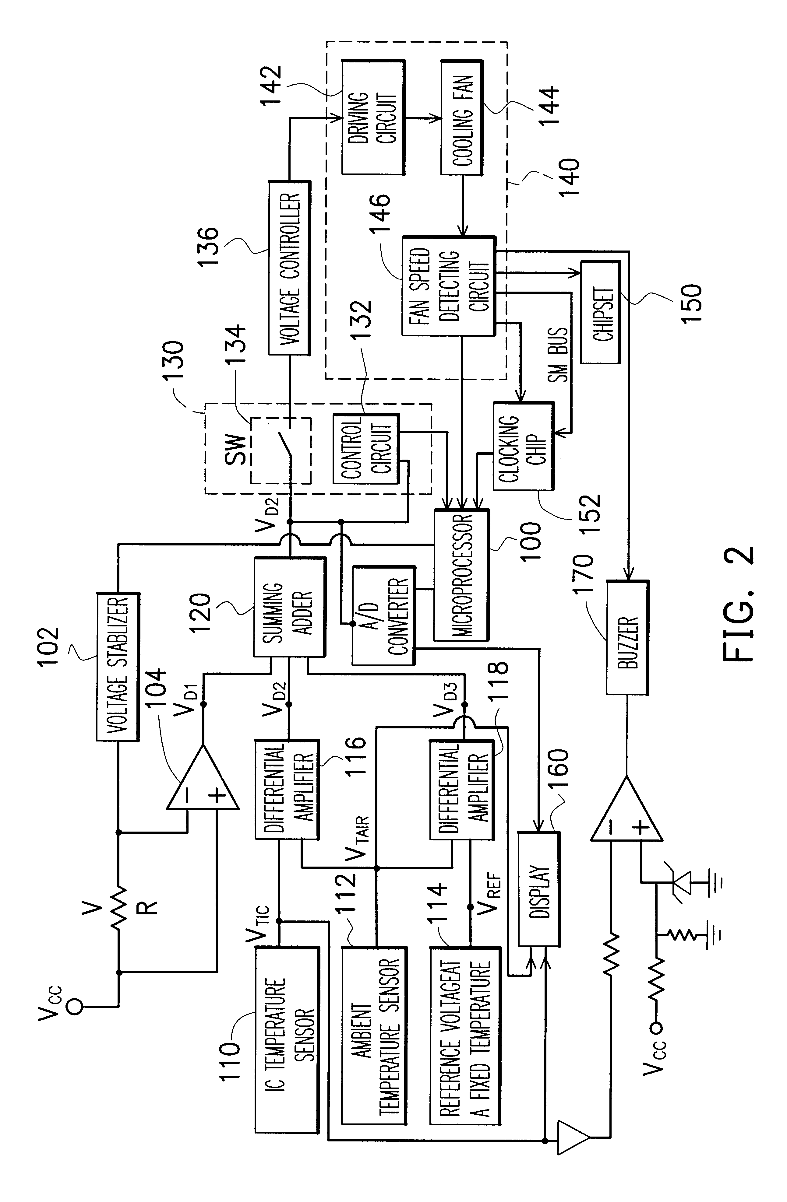
[0025]FIG. 2 is a circuit diagram showing a control circuit of a cooling apparatus of an integrated circuit 100 according to a first embodiment of this invention. The cooling apparatus controls the speed of the cooling fan 144 according to the loading of the integrated circuit 100, the ambient temperature Tair, the temperature TIC of the integrated circuit 100 and a reference temperature TREF. The cooling apparatus contains at least an adder 120, a control means 130 and a cooling fan 140.

[0026]The adder 120 can be a weighted summer used to receive a first voltage signal VD1, a second voltage signal VD2 and a third voltage signal VD3 to generate a control signal VWS. The first voltage signal VD1 refle...


PUM


Abstract

A cooling apparatus for an integrated circuit. The cooling apparatus comprises cooling fan means, a control circuit and heat pipe means. The control circuit determines a spinning speed of the cooling fan and an operation performance mode of the integrated circuit according to the load and the temperature of the integrated circuit, the ambient temperature and a reference temperature. Within a tolerable range of the output of adder means, the heating pipe means continues dispelling heat of the integrated circuit without turning on the cooling fan. While the output of the adder means exceed the tolerable range, the fan is turned on to enforce the heat dissipation.

Description

BACKGROUND OF THE INVENTION[0001]1. Field of Invention[0002]The present invention relates to a cooling device and a control circuit thereof. More particularly, the present invention relates to a device and a control circuit for cooling an integrated circuit (IC) in the application of a microprocessor in a computer system.[0003]2. Description of Related Art[0004]FIG. 1 is a circuit diagram showing a conventional cooling fan control circuit for cooling an integrated circuit. The integrated circuit 11 is connected to a voltage stabilizer 12 which supplies an operation voltage to the integrated circuit 11. The input terminal of the stabilizer 12 is connected to one terminal of a sense resistor 15 as well as the negative (−) input terminal of an operation amplifier 13. The other terminal of the sense resistor 15 is connected to a power source Vcc and the positive (+) terminal of the operation amplifier 13. The output terminal of the operation amplifier 13 is connected to a cooling fan 14...

Claims


Application Information

Patent Timeline
IPC IPC(8): H02H5/00G06F1/20H01L23/34H01L23/467
CPCG06F1/203H01L23/34H01L23/467H01L2924/0002H01L2924/00
Inventor LIU, CHU-KUNG
Owner TWINHEAD INT
Why Eureka
Try Eureka