Gray code counter
a code counter and code technology, applied in the field of gray code counters, can solve the problem that the pattern of the integrated circuit cannot be simplified, and achieve the effect of simple circuit configuration and easy design of circuits with arbitrary bit numbers
- Summary
- Abstract
- Description
- Claims
- Application Information
AI Technical Summary
Benefits of technology
Problems solved by technology
Method used
Image

Examples
first embodiment
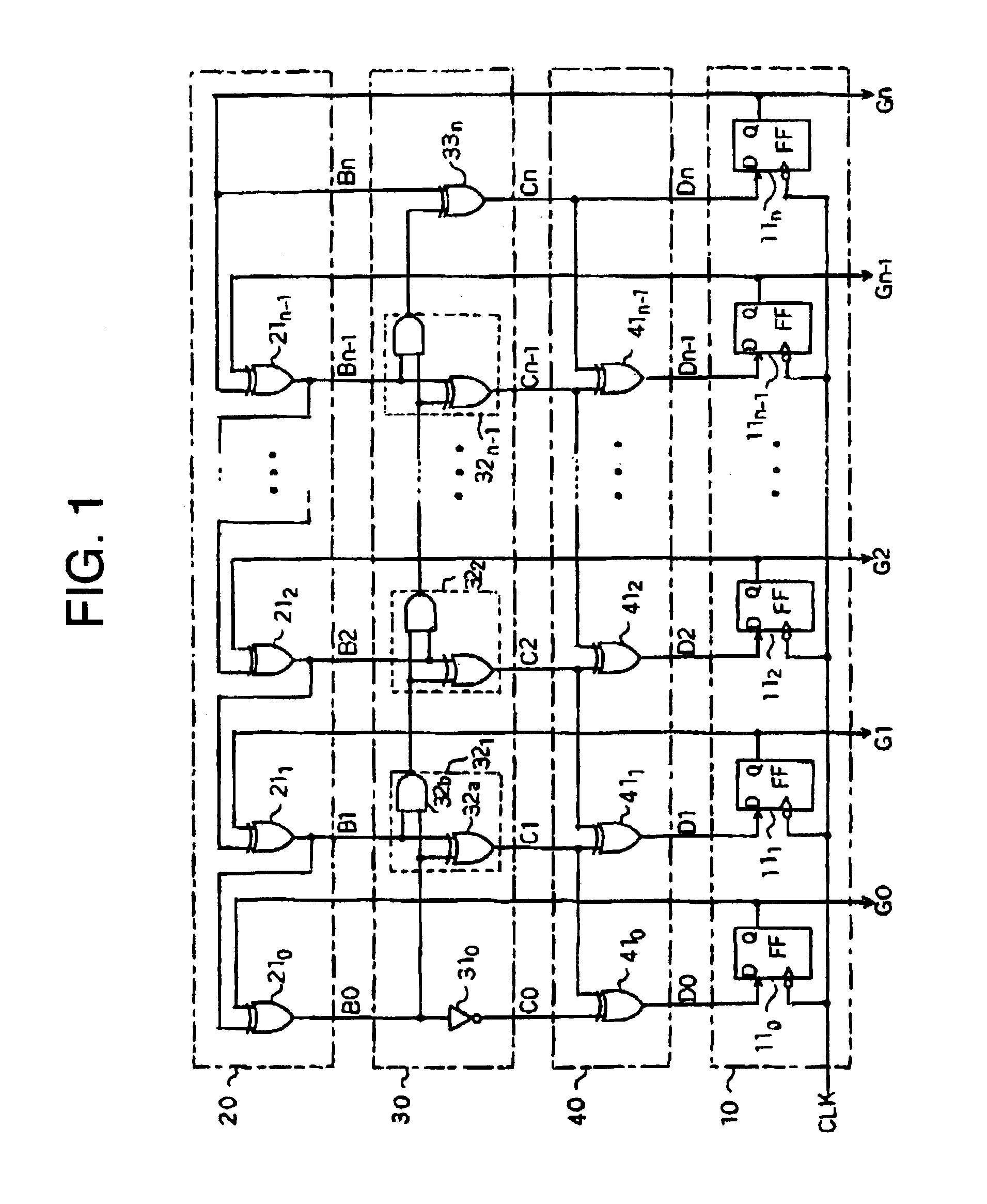
[0020]FIG. 1 is a circuit diagram of a Gray code counter relating to the first embodiment of the invention.
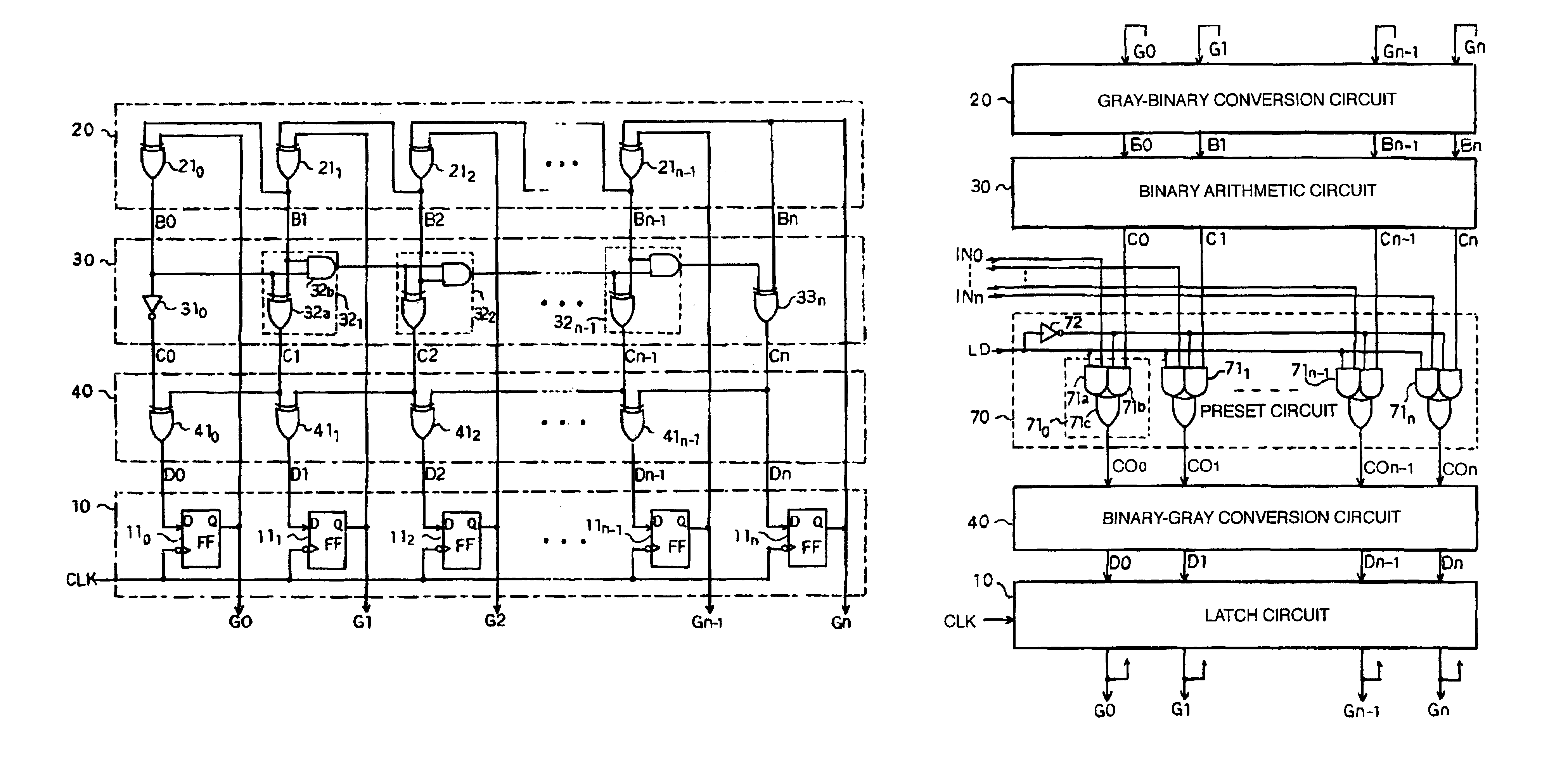
[0021]The Gray code counter includes a holding means (for example, holding circuit) 10, a first conversion means (for example, Gray-binary conversion circuit) 20, an operation means (for example, binary operation circuit) 30, and a second conversion means (binary-Gray conversion circuit) 40.
[0022]The holding circuit 10 holds n+1 bit Gray code signals D0, D1, . . . , Dn given by the binary-Gray conversion circuit 40 at the falling timing of a clock signal CLK, and outputs them as output signals G0, G1, . . . , Gn. The holding circuit 10 possesses DFF110, DFF111, . . . , DFF11n corresponding to each bit. The clock signal CLK is commonly given to these DFF110, DFF111, . . . , DFF11n.
[0023]The Gray-binary conversion circuit 20 converts the Gray code output signals G0, G1, . . . , Gn outputted by the holding circuit 10 into the binary numbers, and outputs the converted results as si...
second embodiment
[0038]FIG. 3 illustrates a binary operation circuit of the second embodiment.
[0039]The binary operation circuit 50 is provided in replacement for the binary operation circuit 30 in FIG. 1, which subtracts 1 from the binary signals B0, B1, . . . , Bn outputted by the Gray-binary conversion circuit 20, and outputs the subtracted results as signals C0, C1, . . . , Cn. The binary operation circuit 50 possesses an INV 510 that inverts the signal B0 of the least significant bit 0 to output the signal C0, subtracting circuits 52j (j=1, 2, . . . , n−1) corresponding to the intermediate bit 1 through bit n−1, and an EOR53n corresponding to the most significant bit n.
[0040]Each of the subtracting circuits 52j is composed of an EOR52a, an INV52b, and an AND52c. In each of the subtracting circuits 52j, the EOR52a executes the exclusive OR operation to a borrow signal given by the lower subtracting circuit 52j−1 and the signal Bj given by the Gray-binary conversion circuit 20 to generate the sig...
third embodiment
[0043]FIG. 4 illustrates a binary operation circuit of the third embodiment.
[0044]The binary operation circuit 60 is provided in replacement for the binary operation circuit 30 in FIG. 1, which increments or decrements the binary signals B0, B1, . . . , Bn outputted by the Gray-binary conversion circuit 20 according to a control signal D / U, and outputs the results as signals C0, C1, . . . , Cn. The binary operation circuit 60 possesses an inverter 61a that inverts the signal B0 of the least significant bit 0 to output the signal C0, an EOR61b that executes the exclusive OR operation to the signal B0 and the control signal D / U, adding / subtracting circuits 62j (j=1, 2, . . . , n−1) corresponding to the intermediate bit 1 through bit n−1, and an EOR63n corresponding to the most significant bit n.
[0045]Each of the adding / subtracting circuits 62j is composed of an EOR62a and an EOR62b, and an AND62c. In each of the adding / subtracting circuits 62j, the EOR62a executes the exclusive OR ope...
PUM
 Abstract
Description
Claims
Application Information