Optical encryption and decryption method and system

a technology of optical encryption and decryption, applied in the field of information security, can solve the problems of affecting the quality of decrypted images, and requiring extremely accurate three-dimensional accuracy, so as to achieve suppressed speckles in decrypted images, the effect of avoiding the requirement of accurate three-dimensional positioning

Inactive Publication Date: 2005-06-14
DANMARKS TEKNISKE UNIV
View PDF6 Cites 35 Cited by
  • Summary
  • Abstract
  • Description
  • Claims
  • Application Information

AI Technical Summary

Benefits of technology

[0022]It is an important advantage of the present invention that the encrypted image may selectively require recording in the mask of phase values or amplitude values or a combination thereof.
[0023]It is another advantage of the present invention that decryption is performed in a plane adjacent to the mask or an equivalent plane whereby generation of speckles in the decrypted image is suppressed.
[0024]It is yet another advantage of the present invention that there is no requirement of positioning a radiation modulator in the Fourier plane whereby an accurate three-dimensional positioning requirement is avoided.
[0025]It is still another advantage of the present invention that only a single key for encryption is required.
[0026]It is preferred to encode the non-encrypte...

Problems solved by technology

It is a disadvantage of the known cryptographic method that encrypting an image both in the object plane and the Fourier plane leads to generation of speckle patterns in the decrypted image thereby corrupting data having been encrypted.
It is another disadvantage of the known cryptograph...

Method used


Image

  • Optical encryption and decryption method and system
  • Optical encryption and decryption method and system
  • Optical encryption and decryption method and system

Examples


example 1

[0128]A very simple example illustrating the individual steps in the above procedure will be given below. To simplify the example it will be considered in one dimension only. The starting point for encoding the encoder in this example is based on the following parameters: {α_=0.5θ=π#⁢ ⁢pix(Δ⁢ ⁢x)=14g⁢ ⁢max=4(20)

[0129]Consider the pixellated 3-step function shown in FIG. 5 to be reconstructed in the image plane as an intensity distribution. From the above choices of parameters one obtains the simple relation between phase values in the encoder and the image intensity values:

|ο(i)|2=2[1−cos(φ(i))]  (21)

[0130]To proceed from here it necessary to calculate the accumulated intensity ∑i ⁢ ⁢o⁢ ⁢(i)2

in the image to be reconstructed. The accumulated intensity is easily calculated from an image histogram where the x-axis represents grey level value and the y-axis represents the amount of pixels in the image at a given grey level value. By use of a histogram ∑i ⁢ ⁢o⁢ ⁢(i)2

is simply found as t...


PUM


Abstract

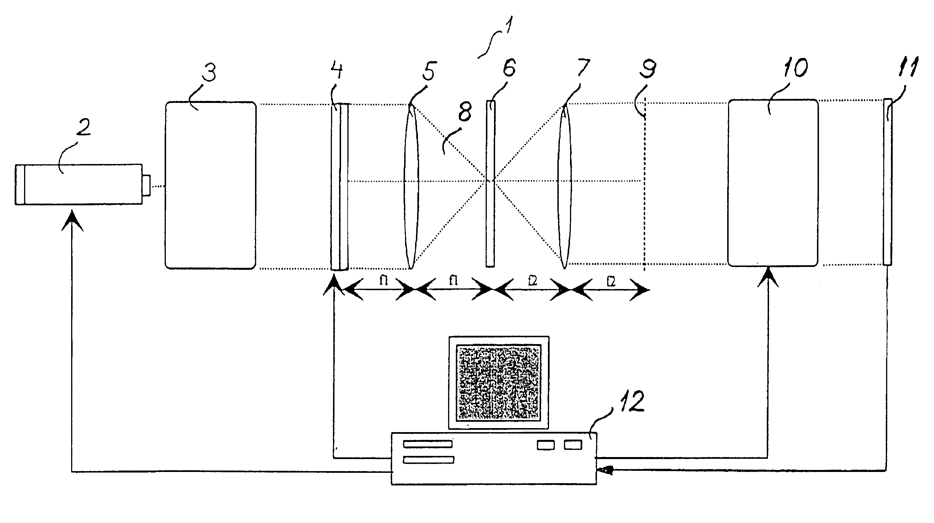
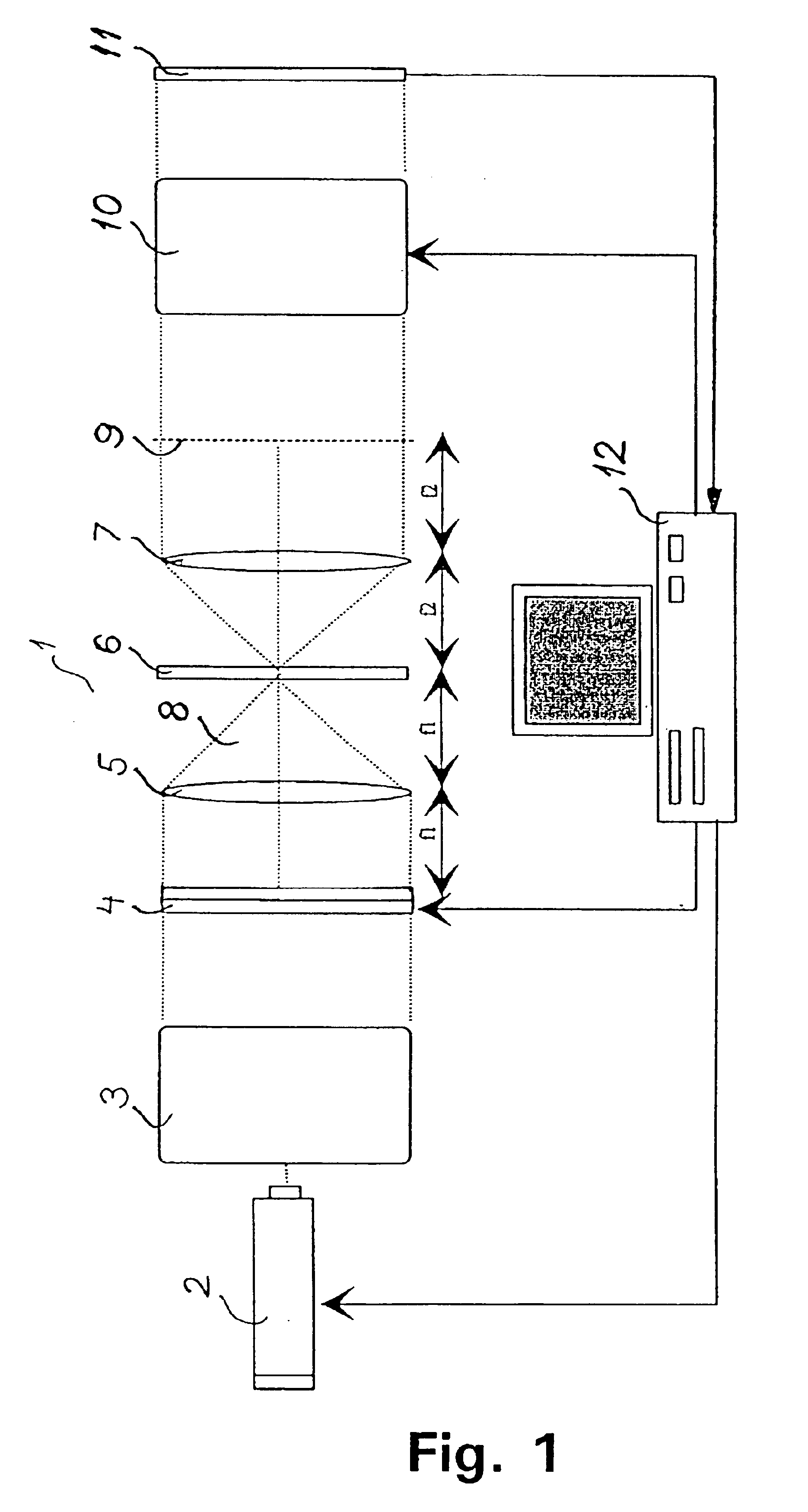
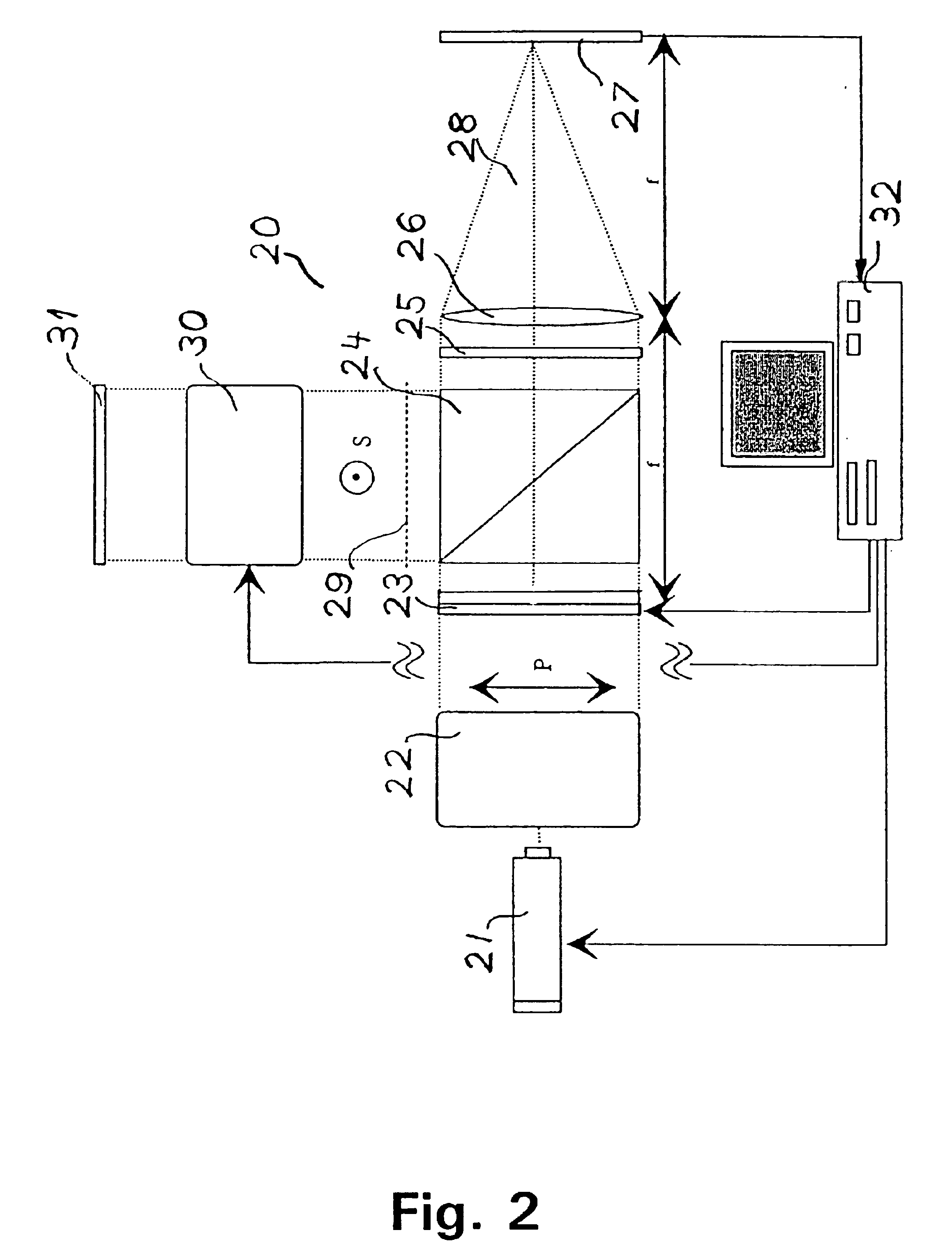
The invention relates to securing of information utilising optical imaging technologies and more specifically to phase encryption and decryption of images. An image is encrypted into a mask having a plurality of mask resolution elements (Xm, Ym) by encoding the image using e.g. a phase mask with an encoded phase value φ (Xm, Ym) and an encoded amplitude value a (Xm, Ym), and by further encrypting the mask (using e.g. a spatial light modulator) by addition of an encrypting phase value φc (Xm, Ym) to the encoded phase value φ (Xm, Ym) and by multiplication of an encrypting amplitude value ac (Xm, Ym) with the encoded phase value a (Xm, Ym). The method of decrypting comprises the steps of decrypting the mask by radiating electromagnetic radiation towards the mask and inserting into the path of the electromagnetic radiation a complex spatial electromagnetic radiation modulator comprising modulator resolution elements, the decrypting phase value φd (Xd, Yd) and the decrypting amplitude value ad (Xd, Yd) respectively, of a modulator resolution element (Xd, Yd) being substantially equal to −φc (Xm, Ym) and ac−1 (Xm, Ym).

Description

[0001]This application is the national phase under 35 U.S.C. § 371 of PCT International Application No. PCT / DK99 / 00331 which has an International filing date of Jun. 16, 1999, which designated the United States of America.FIELD OF THE INVENTION[0002]The invention relates to securing of information utilising imaging technologies and more specifically to phase and amplitude encryption and decryption of images.BACKGROUND OF THE INVENTION[0003]It is well known to form an image by phase contrast imaging methods in which phase modulation of light is converted into intensity modulation. As opposed to intensity modulation, phase modulation does not involve loss of energy.[0004]In published patent application no. WO 96 / 34307, which is hereby incorporated by reference, a phase contrast imaging method is disclosed for calculating phasor values of a phase mask for synthesising a desired intensity pattern.[0005]In “Securing Information with Optical Technologies”, Bahram Javidi, Physics Today, Vo...

Claims


Application Information

Patent Timeline
IPC IPC(8): G02B27/46H04K1/00
CPCH04K1/00G02B27/46
Inventor GLUCKSTAD, JESPER
Owner DANMARKS TEKNISKE UNIV
Why Eureka
Try Eureka