Stable LVDT extensometer

Inactive Publication Date: 2005-06-21
AIR FORCE THE US SEC THE
View PDF15 Cites 20 Cited by
  • Summary
  • Abstract
  • Description
  • Claims
  • Application Information

AI Technical Summary

Benefits of technology

[0012]It is an advantage of the present invention that it can be calibrated to be more sensitive to displacement than prior art extensometers while maintaining a more stable output.
[0013]It is a feature of the present invention that it is made using only one piece, providing the advantage of avoiding the errors in small-scale measurements from gaps at the interfaces between pieces.
[0014]It is another feature of the present invention that its physical geometry is such that all but one of the six degrees of freedom of movement are constrained, providing the advantage that only what is being measured can move.
[0015]It is another advantage of the present invention that its solid flexure configuration avoids hysteresis and non-linearity associated with moving mechanical connections.
[0016]These and other objects, features and advantages of the present invention will become apparent as the description of a representative embodiment proceeds.
[0017]In accordance with the foregoing principles and objects of the present invention, a novel extensometer is described. The unique discovery of the present inv

Problems solved by technology

Variations in strain readings, primarily drift, using such strain gauges have been a problem.
Particularly at the low strain rates used for many composite creep tests, the strain readings over time are affected by many environmental factors.
Electrical interference from the test system itself can cause a high frequency noise band of up to ±150 microstrain.
Although electrical noise is not the source of the gradual changes in strain typically present in such

Method used


Image

  • Stable LVDT extensometer
  • Stable LVDT extensometer
  • Stable LVDT extensometer

Examples


Embodiment Construction

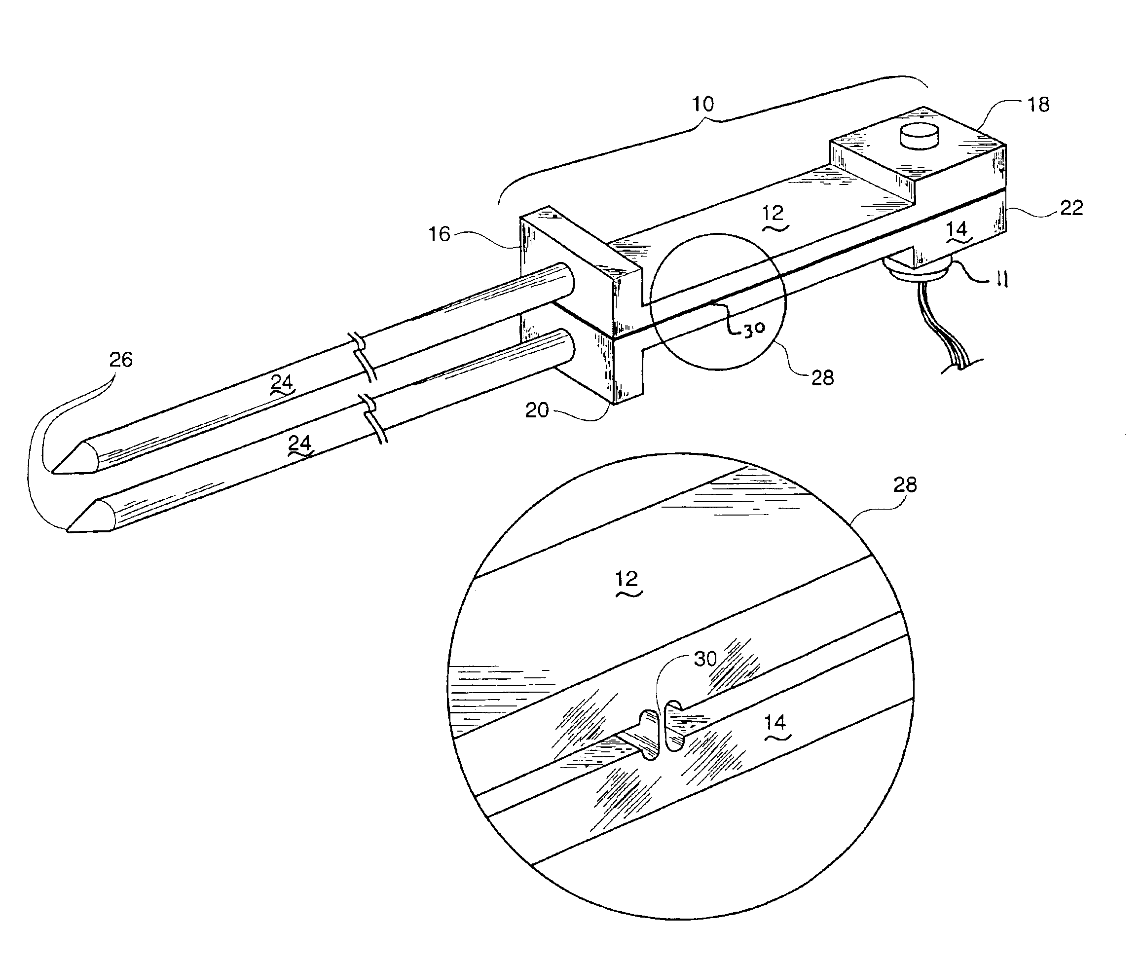
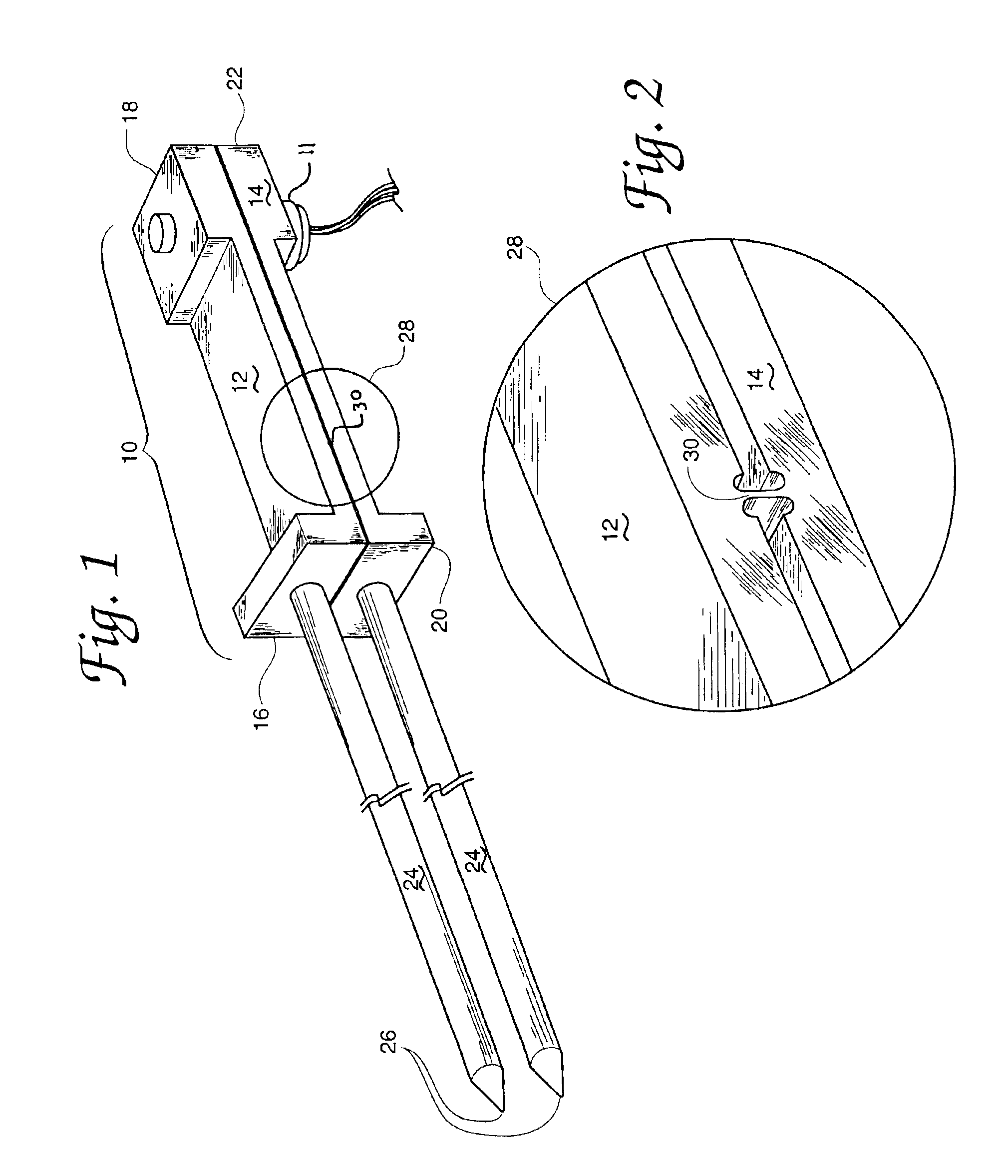
[0025]Referring now to FIG. 1 of the drawings, there is shown a representational view of an LVDT extensometer according to the teachings of the present invention showing a perspective view of an extensometer body 10, an LVDT sensor 11 and a pair of attached specimen contact rods 24 for contacting a specimen to be tested. Extensometer body 10 comprises a first body part 12 and a second body part 14. First body part 12 and second body part 14 each have a long axis at which respective ends 18 and 22 extensometer body 10 is configured for mounting LVDT sensor 11. Similarly, first and second body parts 12 and 14 are each configured at respective other ends 16 and 20 of each long axis for attaching or mounting specimen contract rods 24. Each specimen contact rod 24 includes a tip 26 for contacting a specimen to be tested. Contact rods 24 will typically be made of quartz or other material able to withstand high temperatures. Contact rods 14 are long because in typical use they extend insid...


PUM


Abstract

A new extensometer is disclosed that avoids prior art problems of drift and other problems from variations in temperature, humidity and other environmental factors. Two primary extensometer body parts each hold at one end specimen contact rods and at their other ends a displacement measuring sensor, preferably a linear variable differential transformer. A thin hinge area connects the two body parts into a single piece monolithic construction so that relative movement between the two body parts is restricted to a single rotational degree of freedom.

Description

[0001]This application claims priority under 35 U.S.C. § 119(e) from U.S. provisional application No. 60 / 349,768, filed Jan. 18, 2002, by applicant George A. Hartman, titled “Stable LVDT Extensometer”. The invention description contained in that provisional application is incorporated by reference into this description.RIGHTS OF THE GOVERNMENT[0002]The invention described herein may be manufactured and used by or for the Government of the United States for all governmental purposes without the payment of any royalty.BACKGROUND OF THE INVENTION[0003]The present invention relates generally to extensometers, and more specifically to high temperature extensometers used, for example, for measuring high temperature creep of unidirectional composite materials.[0004]Extensometers measure strain on a test specimen subjected to tensile, compression, fatigue or creep tests. Extensometers generally have a pair of arms connected together with some sort of spacing mechanism. The arms are coupled ...

Claims


Application Information

Patent Timeline
IPC IPC(8): G01B7/16G01L1/22G01N3/06
CPCG01B7/16G01L1/2206G01N2203/0635
Inventor HARTMAN, GEORGE A.
Owner AIR FORCE THE US SEC THE
Why Eureka
Try Eureka