Liquid crystal display device with an ink-jet color filter and process for fabricating the same

a technology of liquid crystal display and color filter, which is applied in non-linear optics, instruments, optics, etc., can solve the problems of reducing the uniform thickness of the color filter, and wasting materials, so as to achieve the effect of reducing the manufacturing cos

Inactive Publication Date: 2005-06-21
LG DISPLAY CO LTD
View PDF4 Cites 58 Cited by
  • Summary
  • Abstract
  • Description
  • Claims
  • Application Information

AI Technical Summary

Benefits of technology

[0012]A further object of the present invention is to provide a simplified method of fabricating a liquid crystal display device that forms an ink-jet color filter through continuous ink ejection.
[0013]Yet another object of the present invention is to provide a simplified method of fabricating a liquid crystal display device with an ink-jet color filter that reduces manufacturing cost by making a color filter using an ink-jet system without a separate barrier structure fabrication process.

Problems solved by technology

The dye method and the pigment dispersion method have an advantage in that they form a fine pattern; but have a drawback in that, since they need a photo-etching process for each of the R, G and B color filters, the fabrication process is complicated and wastes material.
The electro-deposition method also has a drawback in that, since an electro-deposition and a mounting process for each of the R, G and B color filters is repeated, it causes a complication in the fabrication process.
The print method has a problem in that it is difficult to uniformly control the thickness of the color filters.
The liquid crystal display device with the conventional ink-jet color filter, however, has a difficulty in that an ink ejection time must be discretely or discontinuously controlled because ink is injected in each cell area 4 of the lattice-shaped barrier structure 2.

Method used


Image

  • Liquid crystal display device with an ink-jet color filter and process for fabricating the same
  • Liquid crystal display device with an ink-jet color filter and process for fabricating the same
  • Liquid crystal display device with an ink-jet color filter and process for fabricating the same

Examples


Embodiment Construction

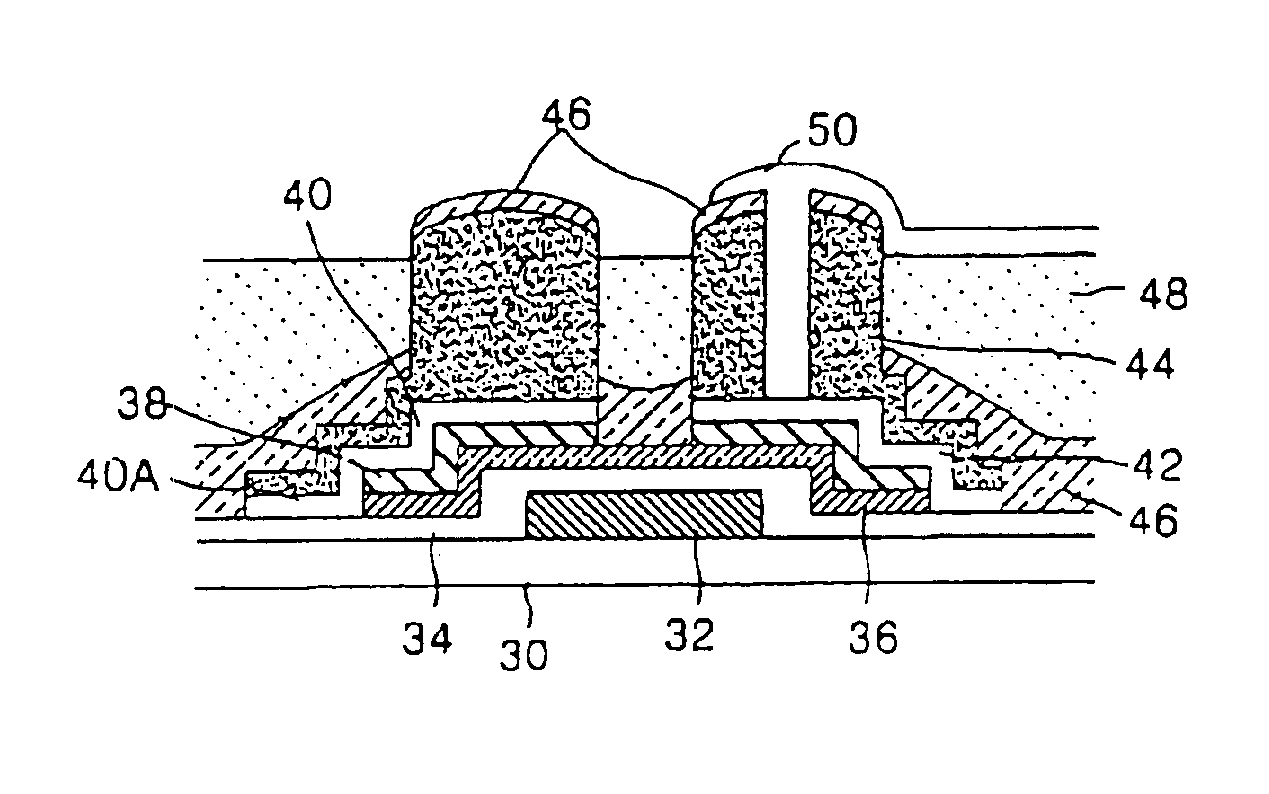
[0030]FIG. 1A is a plan view showing a liquid crystal display device with an ink-jet color filter according to an embodiment of the present invention. FIG. 3B is a sectional view of the liquid crystal display device taken along line 3B—3B in FIG. 3A. In FIGS. 3A and 3B, the liquid crystal display device with the ink-jet color filter includes thin film transistors provided at each intersections of gate lines 32A and data lines 40A, barrier ribs 44 formed in the same pattern as a source electrode 40 and a drain electrode 42 of the thin film transistor, a color filter 48 provided between the barrier ribs 44, and a pixel electrode 50 provided on the upper portion of the color filter 48. The thin film transistor consists of a gate electrode 32 extended from the gate line 32A, a source electrode extended from the data line 40A, and an active layer 36 providing with a current channel between the source and drain electrodes 40 and 42.

[0031]The barrier ribs 44 are photo-resist patterns defin...


PUM

PropertyMeasurementUnit
dielectric constantaaaaaaaaaa
areaaaaaaaaaaa

Abstract

Barrier lines are formed on a substrate to define column areas between adjacent barrier lines. A color filter is then formed using continuous ink ejection in at least one of the column areas.

Description

BACKGROUND OF THE INVENTION[0001]1. Field of the Invention[0002]This invention relates to a liquid crystal display device, and more particularly to a liquid crystal display device using a color filter formed in an ink-jet printing system and a process of fabricating the same.[0003]2. Description of the Related Art[0004]Generally, a liquid crystal display device, widely used as a flat panel display of active matrix driving system, divides a light generated at a light source into light of three basic colors, red (R), green (G), and blue (B), so as to display a color picture. To this end, the liquid crystal display device requires a red (R) filter for transmitting the red light only, a green (G) filter for transmitting the green light only and a blue (B) filter for transmitting the blue light only for each picture element (or pixel). The R, G and B filters must not overlap with each other in order to prevent the deterioration of the picture and the color spread.[0005]Methods of fabrica...

Claims


Application Information

Patent Timeline
Patent Type & Authority Patents(United States)
IPC IPC(8): G02F1/1335G02F1/13G02F1/1362
CPCG02F1/136209G02F2001/136222G02F1/136222
Inventor YI, JONG HOONKIM, JEONG HYUNOH, SANG HUNKIM, SOO MAHNLEE, SANG GUL
Owner LG DISPLAY CO LTD
Why Eureka
Try Eureka