Magnetic transfer apparatus

a transfer apparatus and magnetic technology, applied in the direction of maintaining the alignment of the head carrier, the magnetic body, instruments, etc., can solve the problems of deformation, poor signal quality, and difficulty in obtaining a uniform close contact between the closely contacted surfaces of the master carrier and the slave medium, so as to avoid defective close contact, prevent generation of transfer inferiority, and good transfer quality

Inactive Publication Date: 2005-06-21
FUJIFILM CORP +1
View PDF4 Cites 1 Cited by
  • Summary
  • Abstract
  • Description
  • Claims
  • Application Information

AI Technical Summary

Benefits of technology

[0035]As apparent from the aforementioned analysis of close contact mode, because local and symmetrical omission of signals was generated in connection with the shape of holder, a shape for uniformly applying force was needed, and by designing the holder in the circular shape, the local and symmetrical omission of signals was not occurred. By setting the circularity of holder to 98% or more, the omission of signals was more largely reduced. In order to reduce the omission of signals further more, it is required to enhance the mechanical strength of magnetic field of holder, and in order to enhance the mechanical strength it is important to use a material with a high Young's modulus E and to increase the thickness d of structure. Herein, as a result of evaluation of signal omission using material and thickness as parameters, when the thickness of holder was set below 3 mm, the deformation was increased and it was difficult to obtain a uniform close contact between the closely contacted surfaces of master carrier and slave medium.
[0056]That is, if the holder surface is formed with high precision of flatness not more than 1 μm and fluctuation range of tip ends of fine prominences not more than 0.01 μm the flatness of master carrier can be secured and its close contact capability with the slave medium can be enhanced, thereby preventing the generation of signal omission. Furthermore, by forming the surface somewhat roughly to have centerline mean surface roughness Ra in the range of 0.1˜1 μm, the inflow and discharge of air will be promoted by the space formed by unevenness of the surface, thereby preventing the air accumulation caused by air remained in the state of close contact with the master carrier and allowing easy separation after the close contact. If the centerline mean surface roughness is below 0.1 μm, problems will be arisen in connection with air accumulation and separability, and if the centerline mean surface roughness exceeds 1 μm, local deformation of master carrier will be generated and cause defectiveness of close contact because the surface is too rough.

Problems solved by technology

Herein, as a result of evaluation of signal omission using material and thickness as parameters, when the thickness of holder was set below 3 mm, the deformation was increased and it was difficult to obtain a uniform close contact between the closely contacted surfaces of master carrier and slave medium.
However, it was found that if the thickness of holder is designed to exceed 15 mm, the quality of signals is degraded although omission of signal is not substantially occurred.

Method used


Image

  • Magnetic transfer apparatus
  • Magnetic transfer apparatus
  • Magnetic transfer apparatus

Examples


Embodiment Construction

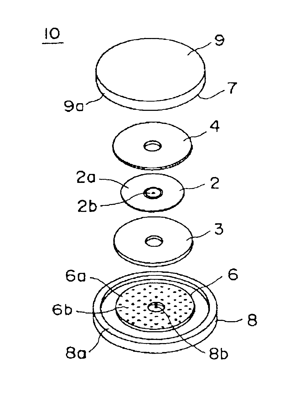
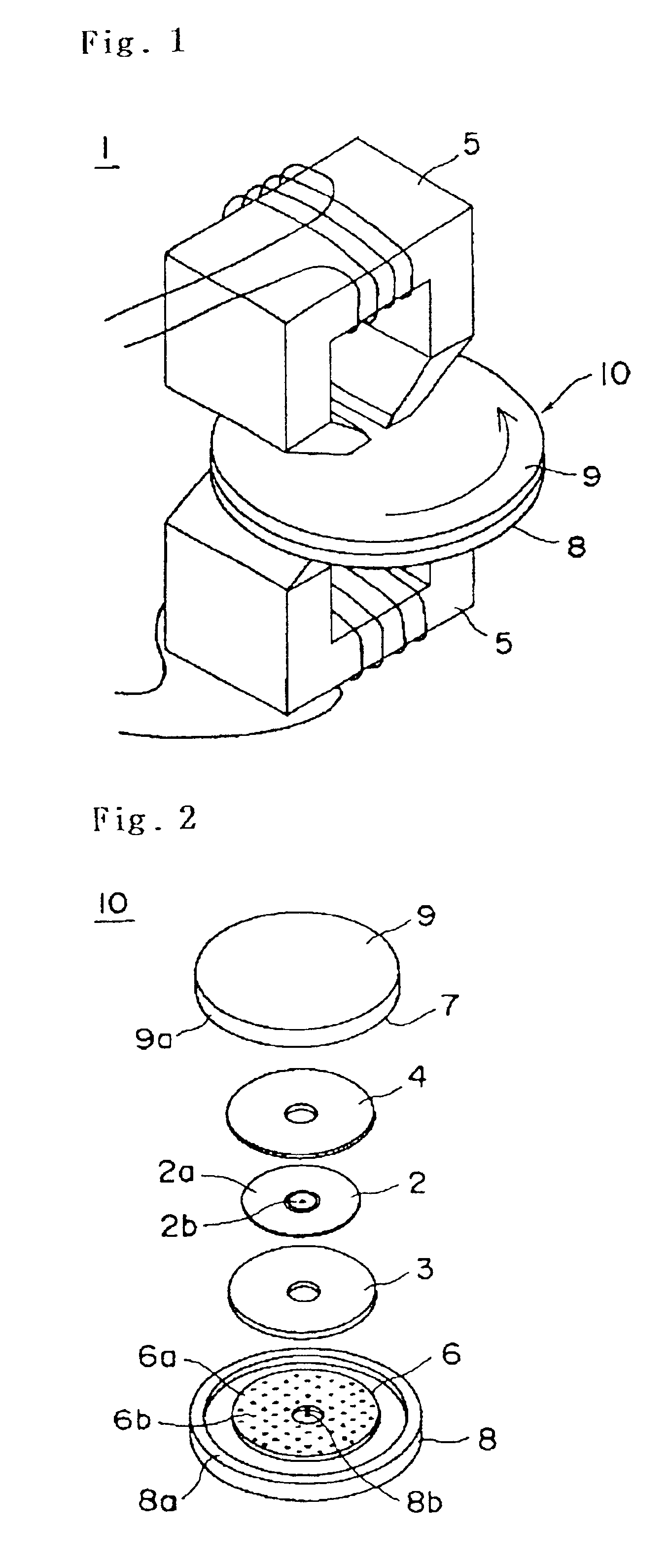
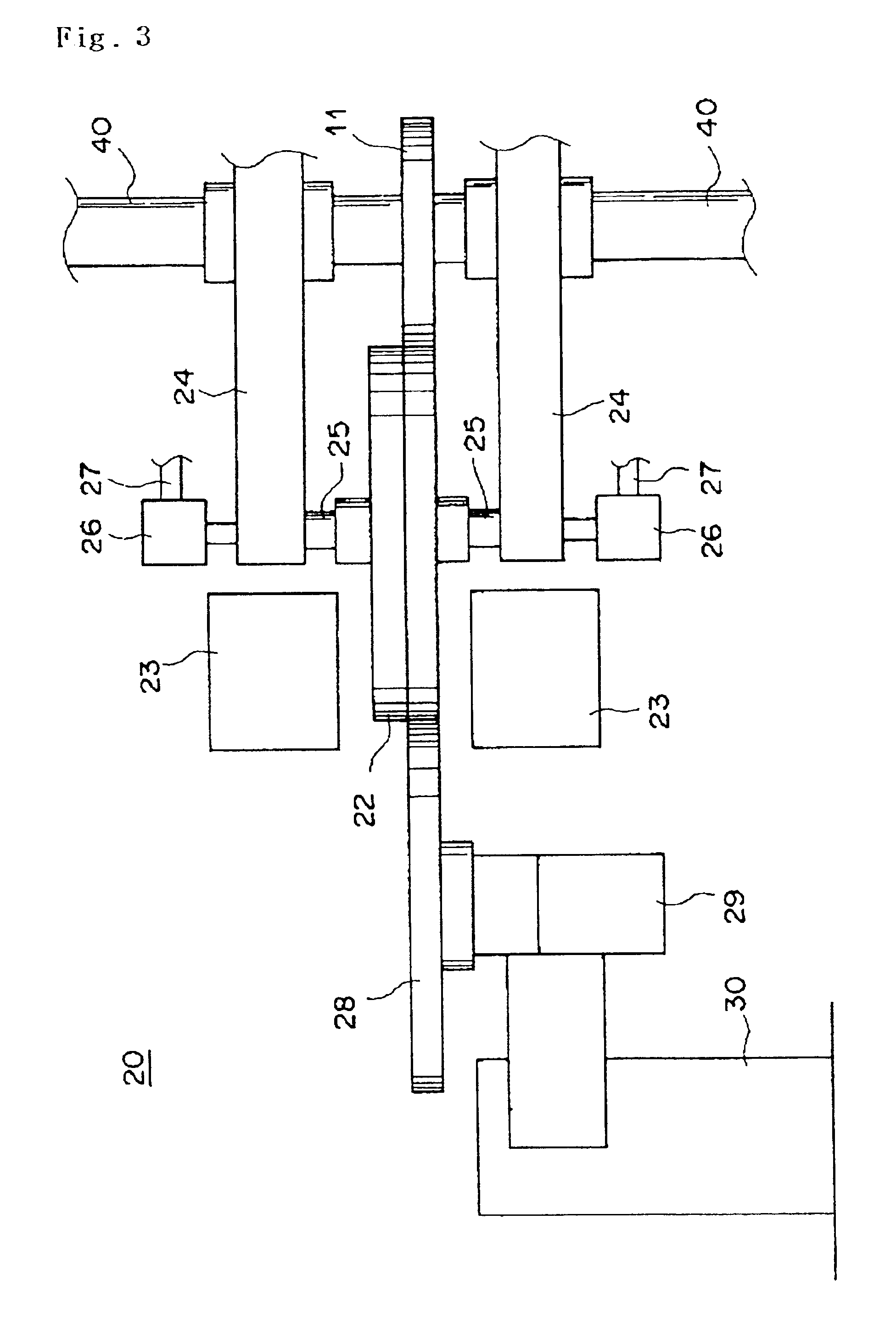
[0062]Herein below, an embodiment of the present invention will be described in detail. FIG. 3 is a front view of main parts showing transfer state of magnetic transfer apparatus according to an embodiment of the present invention. The members installed within the holder such as the master carrier, slave medium and the like are described in detail in the above and the description thereof will be omitted.

[0063]The magnetic transfer apparatus 20 shown in FIG. 3 executes simultaneous both side transfer by inplane recording technique, in which magnetic field for transfer is applied by a magnetic field applying apparatus 23 (electromagnetic devices) located upper and lower sides of a holder 22 (identical to the holder 10 shown in FIG. 1) while rotating the holder 22 which has brought master carriers into confronted close contact with upper and lower sides of a slave medium, whereby information born in the master carrier is magnetically transferred and recorded onto both sides of slave me...


PUM

PropertyMeasurementUnit
diametersaaaaaaaaaa
thicknessaaaaaaaaaa
thicknessaaaaaaaaaa

Abstract

By bring a master carrier and a slave medium into close contact with uniform force when executing magnetic transfer by applying transfer magnetic field in the state that the master carrier and slave medium is in confronted close contact and received within a holder, inferiority of transfer such as omission of signals is prevented and quality of transfer signals is enhanced.The magnetic transfer apparatus executes magnetic transfer by applying transfer magnetic field by means of a magnetic field applying apparatus 5 after a master carrier 3, 4 bearing transfer information and a slave medium 2 to be transferred are brought into confronted close contact and received within a holder 10, wherein said holder 10 has a substantially circular shape and in particular, the circularity of holder is not less than 98%, wherein the flexural rigidity=Ed3 / 12 determined by Young's modulus E and thickness d of the holder is in the range of 0.1˜30 kN·m2 when the width of close contact area between the slave medium and master carrier is defined as 1m, and wherein the practical thickness of the holder is not less than 3 mm and not more than 15 mm.

Description

TECHNICAL FIELD[0001]The present invention relates to a magnetic transfer apparatus for executing magnetic transfer from a master carrier bearing information to a slave medium.BACKGROUND OF THE INVENTION[0002]In general, as amount of information is increased, a magnetic recording medium is demanded which is of mass storage to record a large quantity of information as well as low-priced, and preferably enables so-called high speed access that can read out necessary part within a short time. As an example of such a medium, a high-recording density flexible disc is known, and so-called tracking servo technique, in which a magnetic head accurately scans a narrow track width and generates signals with a high S / N ratio, is playing an important role for realizing such mass storage. In one revolution of disc, a servo tracking signal, an address information signal, a regenerative clock signal and the like are recorded in a predetermined space in so-called pre-format.[0003]The magnetic head i...

Claims


Application Information

Patent Timeline
Patent Type & Authority Patents(United States)
IPC IPC(8): G11B5/86G11B5/82G11B5/596
CPCB82Y10/00G11B5/743G11B5/865G11B5/59633Y10T428/12465Y10T428/32G11B5/82G11B5/86
Inventor NISHIKAWA, MASAKAZUNIITSUMA, KAZUHIROKAMATANI, AKITO
Owner FUJIFILM CORP
Why Eureka
Try Eureka