High voltage capacitor and magnetron

a high-voltage capacitor and magnetron technology, applied in the direction of feed-through capacitors, fixed capacitor details, transit-tube leading-in arrangements, etc., can solve the problems of dielectric ceramic material expanding, gap formation, dielectric ceramic material deterioration, etc., to avoid deterioration of characteristics and electrical short circulation, increase bonding force, and high reliability

Active Publication Date: 2005-06-21
TDK CORPARATION
View PDF6 Cites 5 Cited by
  • Summary
  • Abstract
  • Description
  • Claims
  • Application Information

AI Technical Summary

Benefits of technology

[0013]It is an object of the present invention to provide a high-voltage capacitor achieving a high degree of reliability in which deterioration of the characteristics and electrical short circulation are avoided by increasing the bonding forces at the interfaces between the insulating case and the insulating resin portion filling the inside of the case and between the grounding metal and the insulating resin portion filling the inside of the case and the bonding force at the interface between the capacitor and the insulating resin portion filling the space around the capacitor, and thus preventing separation at the interfaces, and to provide a magnetron utilizing the high-voltage capacitor as a filter.
[0022]Furthermore, since the insulating resin fills the space inside the insulating case, the internal space of the grounding metal and the space around the capacitor, a higher degree of reliability is achieved in reliability tests such as high temperature load tests and moisture resistance load tests or when the high-voltage capacitor is used in a hot and highly humid environment.
[0024]The brominated aromatic glycidyl ether, which is in the form of liquid, comprises small-size particles. Consequently, prevention of particle settling is achieved, which ensures complete contact at the interface of the insulating resin. This increases the bonding forces at the interfaces between the insulating case and the insulating resin portion filling the inside of the case and between the grounding metal and the insulating resin portion filling the inside of the case, and the bonding force at the interface between the capacitor and the insulating resin portion filling the space around the capacitor. Consequently, it is fully possible to withstand the mechanical stress attributable to the hardening / contraction of the insulating resin or the electrostrictive phenomenon occurring at the dielectric ceramic material during use. This provides a high-voltage capacitor achieving a high degree of reliability in which deterioration of the characteristics and electrical short circulation are avoided by increasing the bonding forces at the interfaces between the insulating case and the insulating resin portion filling the inside of the case and between the grounding metal and the insulating resin portion filling the inside of the case and the bonding force at the interface between the capacitor and the insulating resin portion filling the space around the capacitor, and thus preventing separation at the interfaces.

Problems solved by technology

As a result, the stress which occurs while the insulating resin is becoming hardened and contracting, and the stress which repeatedly occurs during operation of the high-voltage capacitor, cause a gap to form between the insulating resin and the dielectric ceramic material and also induce formation of a gap between the insulating resin and the internal circumferential surface of the insulating case and between the insulating resin and the grounding metal.
This results in the dielectric ceramic material expanding while the voltage is being applied and contracting to regain its original state when the voltage is not applied.
Thus, high-voltage capacitors of this type in the prior art pose a risk of early defects occurring due to deterioration of characteristics and short circulation occurring between electrodes.
Another cause of deterioration of characteristics includes settling of a fire retardant into a groove formed in the dielectric ceramic material.
As a result, the fire retardant is liable to settle onto the insulation interface to be unevenly distributed.
The fire retardant itself is inferior to the base resin in insulating property and also adversely affects the bonding strength of the dielectric ceramic material and the base resin.
In addition, the settling of the fire retardant causes problems such as variations in initial breakdown voltage and relatively early deterioration in high temperature load property.

Method used


Image

  • High voltage capacitor and magnetron
  • High voltage capacitor and magnetron
  • High voltage capacitor and magnetron

Examples


Embodiment Construction

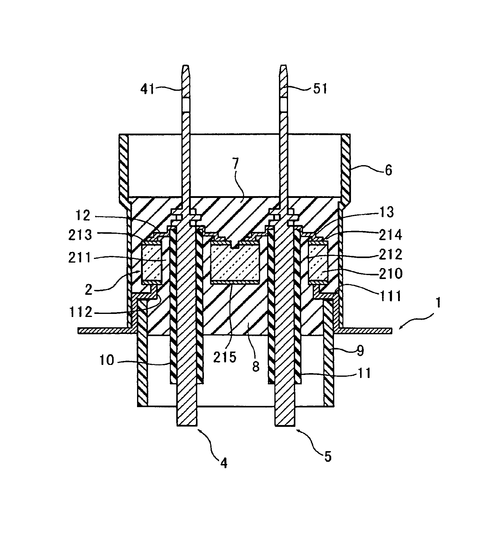
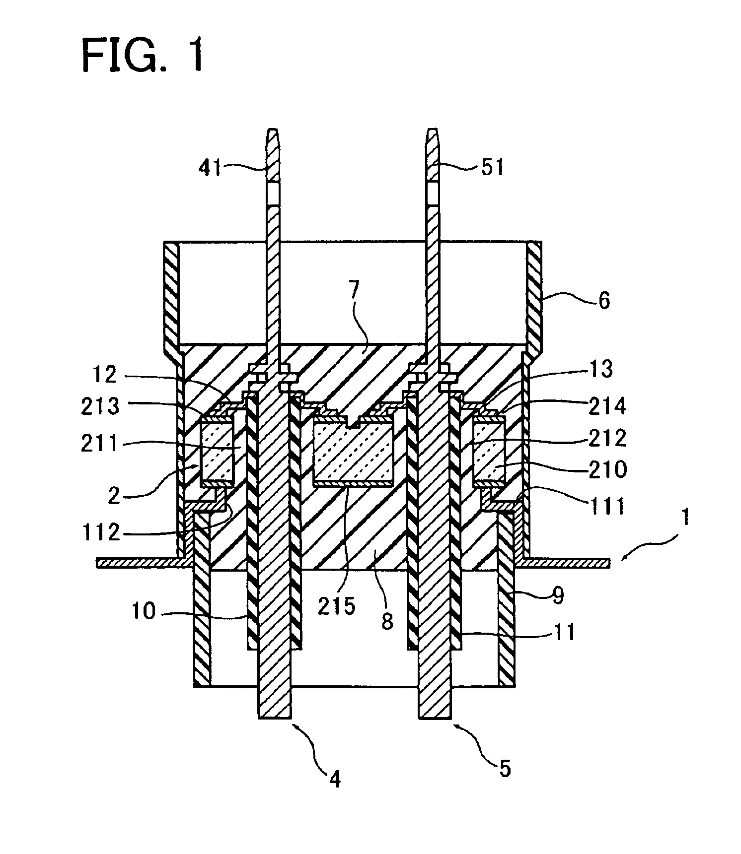
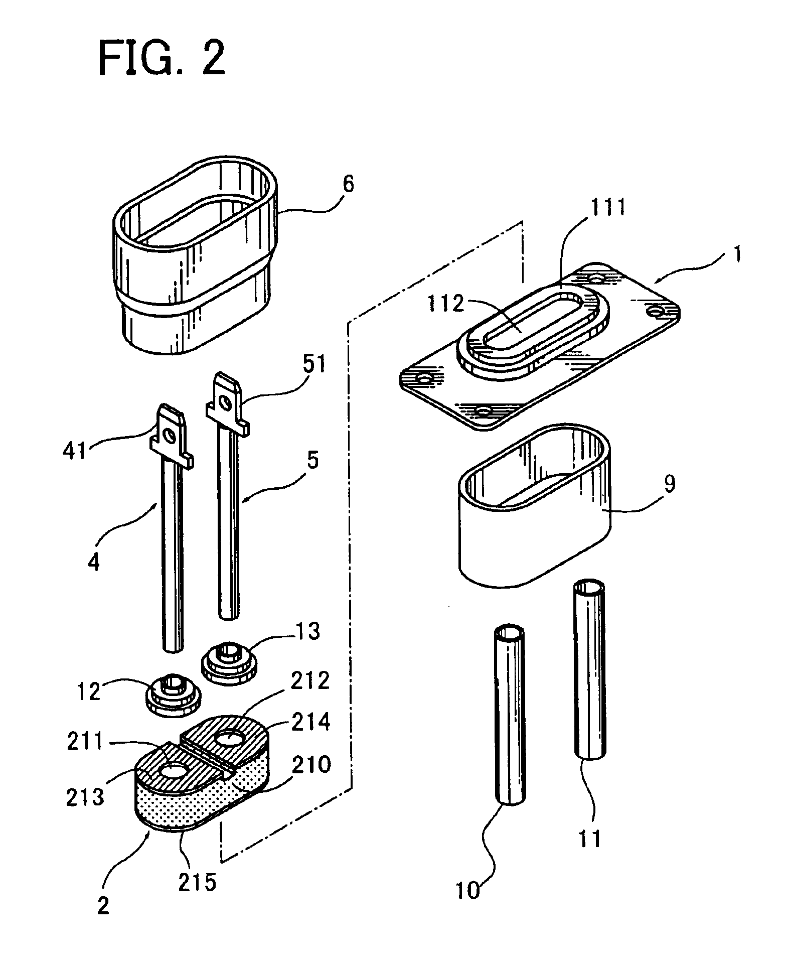
[0031]Referring to FIGS. 1 and 2, the high-voltage capacitor includes a grounding metal 1, a capacitor 2, through conductors 4 and 5, an insulating case 6, an outer insulating resin 7, an inner insulating resin 8, an insulating cover 9 and insulating tubes 10 and 11 constituted of silicon or the like.

[0032]The grounding metal 1 has a raised portion 111 at one surface thereof, with the raised portion 111 having a through hole 112. The capacitor 2 is provided on the raised portion 111 and an electrode 215 of the capacitor is secured to the raised portion 111 by a means such as soldering. The through conductors 4 and 5 pass through the through holes 211 and 212 of the capacitor 2 respectively and also through the through hole 112 of the grounding metal 1 and are connected to electrodes 213 and 214 respectively via electrode conductors 12 and 13 achieving electrical continuity.

[0033]The outer insulating resin 7 fills the space around the capacitor 2 at one surface of the grounding metal...


PUM

PropertyMeasurementUnit
frequencyaaaaaaaaaa
temperatureaaaaaaaaaa
breakdown voltageaaaaaaaaaa

Abstract

A capacitor has electrodes at surfaces thereof, with one of the electrodes secured onto one surface of a grounding metal. Through conductors pass through the capacitor and the grounding metal and are connected to the other electrodes so as to achieve electrical continuity. An insulating case is provided at one surface of the grounding metal, with one end of the insulating case fitted around the external circumference of the raised portion of the grounding metal. Insulating resin fills a space inside the insulating case, the internal space of the grounding metal and a space around the capacitor. The insulating resin comprises an epoxy resin containing a brominated fire retardant, and the brominated fire retardant is a brominated aromatic glycidyl ether.

Description

BACKGROUND OF THE INVENTION[0001]1. Field of the Invention[0002]The present invention relates to a high-voltage capacitor and a magnetron having a filter constituted of the high-voltage capacitor.[0003]2. Discussion of Background[0004]Well-known examples of high-voltage capacitors of this type in the prior art include those disclosed in Japanese Unexamined Patent Publication No. 1996-316099 and Japanese Unexamined Utility Model Publication No. 1992-40524. They have the following structural features in common. Two through holes are formed over a distance from each other at a dielectric ceramic material to constitute the capacitor. Individual electrodes that are independent of each other and a common electrode to be shared by the individual electrodes are provided at the two surfaces of the dielectric ceramic material at which the through holes open. The common electrode is fixed on a raised portion of a grounding metal by a means such as soldering. Through conductors are provided so ...

Claims


Application Information

Patent Timeline
Patent Type & Authority Patents(United States)
IPC IPC(8): H01G4/002H01G4/35H01G4/224H01G4/40H01J23/15H01G4/12H01J23/00
CPCH01G4/35
Inventor SATO, TSUKASAFUJIWARA, ISAOMORITA, MAKOTOHORIKAWA, KENICHI
Owner TDK CORPARATION
Why Eureka
Try Eureka