
Method of uprating an existing nuclear power plant

Inactive Publication Date: 2005-06-21
WESTINGHOSE ELECTRIC CORP
View PDF17 Cites 36 Cited by
  • Summary
  • Abstract
  • Description
  • Claims
  • Application Information

AI Technical Summary

Benefits of technology

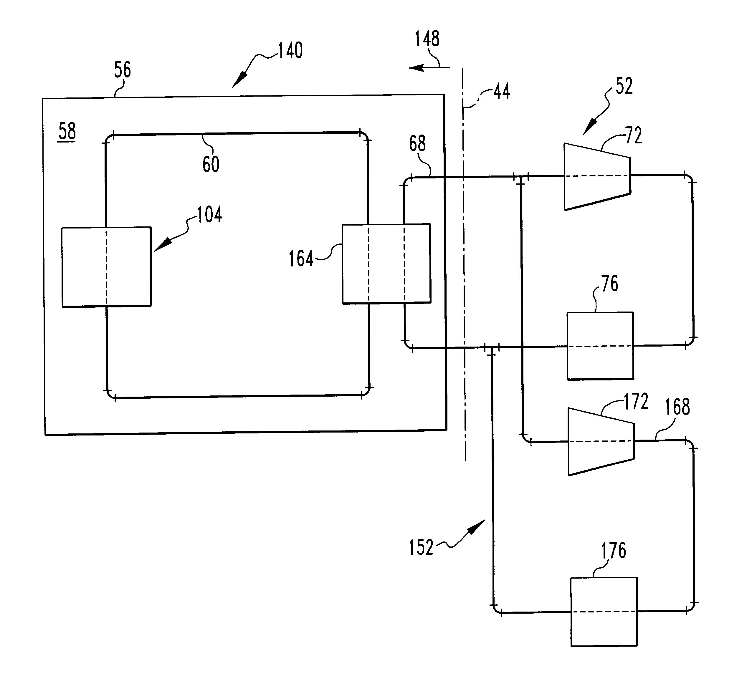
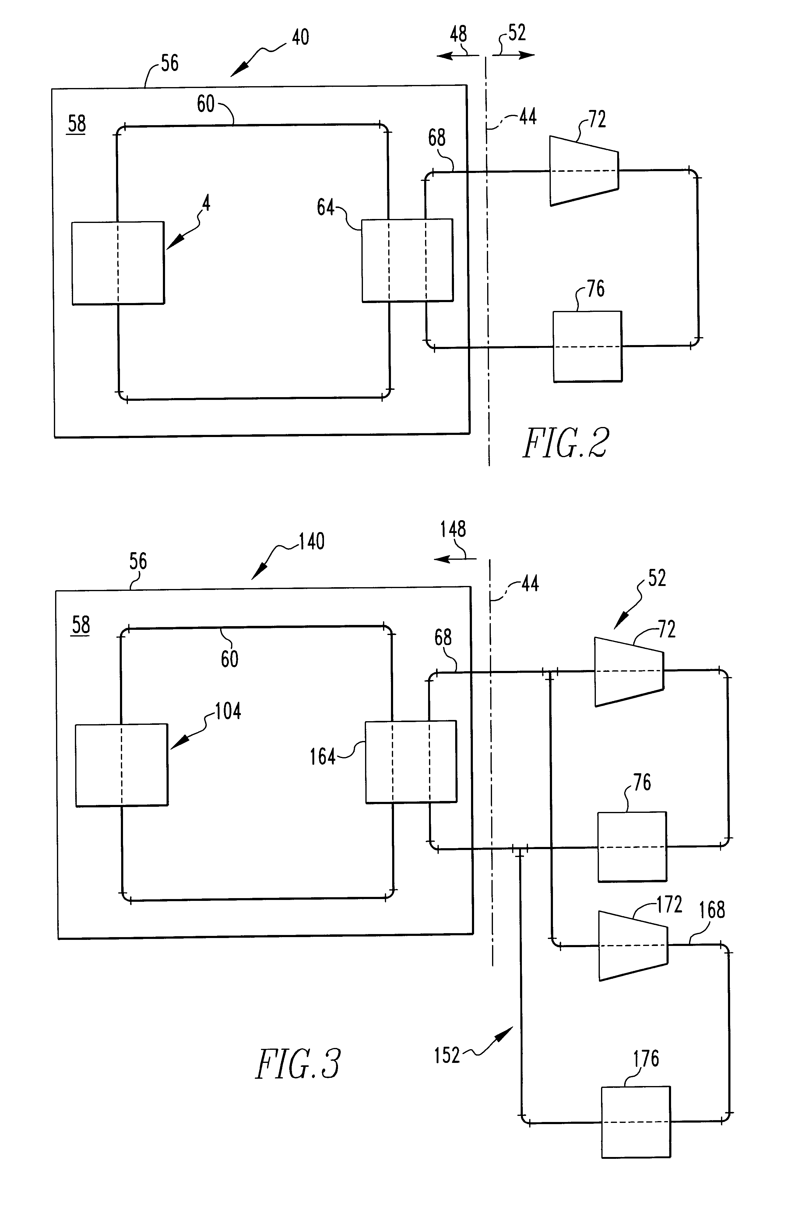
[0009]In view of the foregoing, an improved method in accordance with the present invention of increasing the power output of an existing nuclear power plant includes increasing the thermal power output of the plant's nuclear island and constructing of an auxiliary BOP to handle the increased thermal power. The thermal power of the nuclear island can be increased such as by increasing the thermal power of the plant's reactor, by replacing the plant's steam generator with one that is more efficient and / or has a relatively greater heat transfer area, and / or by increasing the flow rate of a coolant in a secondary cooling loop of the plant. The thermal power of the reactor can be increased such as by replacing existing cylindrical fuel rods with fuel rods having a relatively greater surface area to volume ratio. The increased thermal power can be transmitted from the reactor to the steam generator by increasing the flow rate and / or the change in temperature of a coolant of a primary cooling loop flowing through the reactor. The auxiliary BOP can be constructed while the plant is in operation, and can then be connected with the nuclear island during a maintenance operation on the reactor. To prolong the life of the nuclear fuel at such relatively higher power levels, one or more methodologies may be employed, such as by installing reflectors that decrease the loss of neutrons from the core, by using relatively longer fuel rods, by providing a higher enrichment of the U235 in the fuel, and by providing a different type of fuel such as uranium nitride (UN).

Problems solved by technology

However, a given nuclear power plant cannot be operated above its licensed power.

Method used


Image

  • Method of uprating an existing nuclear power plant
  • Method of uprating an existing nuclear power plant
  • Method of uprating an existing nuclear power plant

Examples


Embodiment Construction

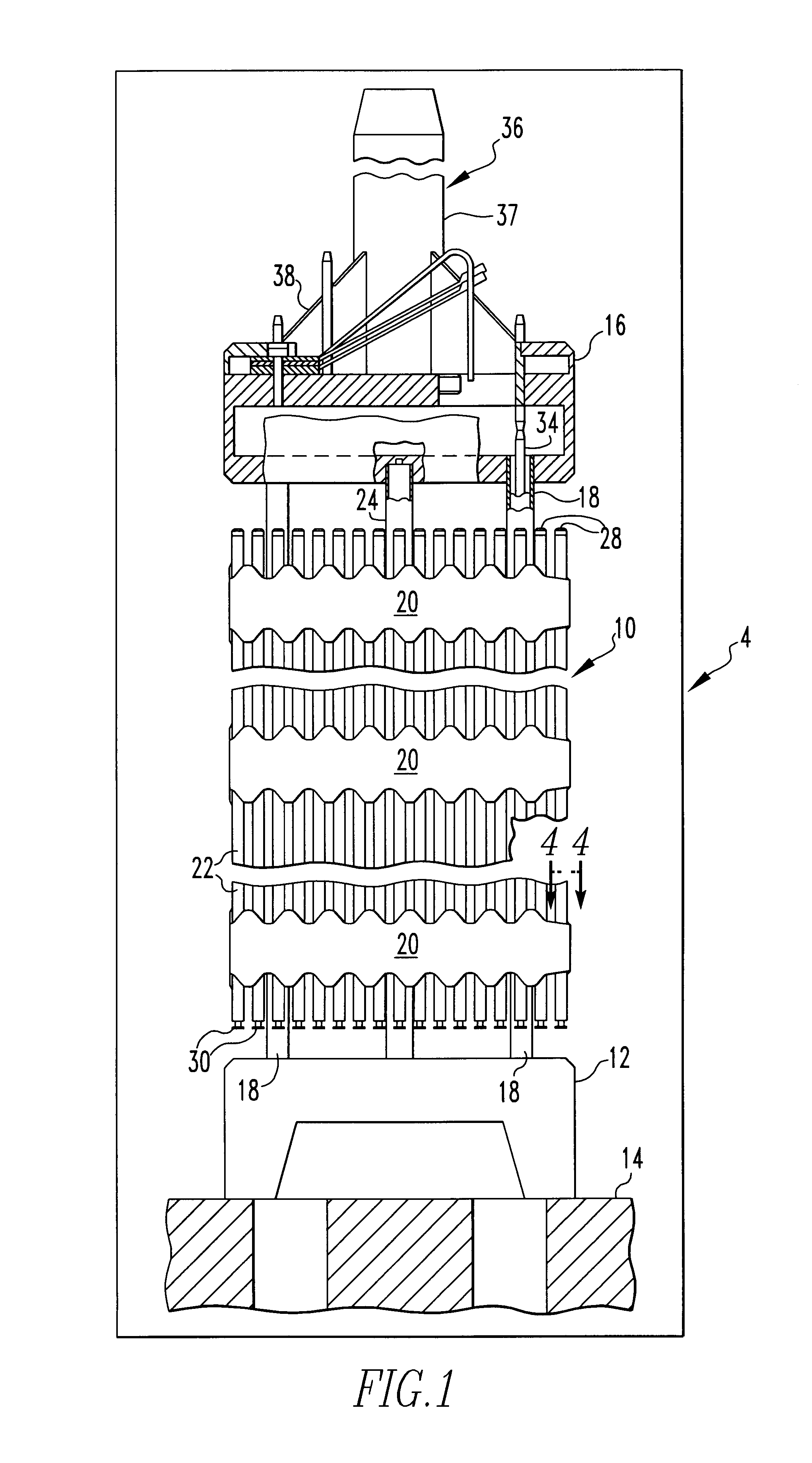
[0049]An exemplary fuel assembly 10 mounted in a schematically depicted nuclear reactor 4 is depicted generally in FIG. 1. One or more of the various components of the fuel assembly 10 and / or other components can be referred to as the internals of the reactor 4.

[0050]The fuel assembly 10 includes a bottom nozzle 12 that supports the fuel assembly 10 on a lower core support plate 14 in the core region of the nuclear reactor 4. The nuclear reactor 4 is a pressurized water reactor that includes a plurality of the fuel assemblies 10 disposed on the core support plate 14. In addition to the bottom nozzle 12, the structural skeleton of the fuel assembly 10 also includes a top nozzle 16 at its upper end and a number of elongated guide tubes or thimble tubes 18 which extend longitudinally between the bottom and top nozzles 12 and 16 and at opposite ends are connected therewith.

[0051]The fuel assembly 10 further includes a plurality of transverse grids 20 axially spaced along and mounted to ...


PUM


Abstract

An improved method of increasing the power output of an existing nuclear power plant includes increasing the thermal power output of the plant's nuclear island and constructing of an auxiliary BOP to handle the increased thermal power. The thermal power of the nuclear island can be increased such as by increasing the thermal power of the plant's reactor, by replacing the plant's steam generator with one that is more efficient, and by increasing the flow rate and / or change in temperature of a coolant in a secondary cooling loop of the plant. The thermal power of the reactor can be increased such as by replacing existing cylindrical fuel rods with fuel rods having a relatively greater surface area to volume ratio and / or by increasing the flow rate and / or the change in temperature of a coolant of a primary cooling loop. The auxiliary BOP can be constructed while the plant is in operation, and can then be connected with the nuclear island during a maintenance operation on the reactor.

Description

BACKGROUND OF THE INVENTION[0001]1. Field of the Invention[0002]The present invention relates generally to nuclear power plants and, more particularly, to a method of increasing the electrical power output of an existing nuclear power plant.[0003]2. Description of the Related Art[0004]Nuclear power plants may be of various configurations. One type of nuclear power plant employs a nuclear reactor to generate steam which is employed to turn one or more turbines that operate electrical generators. One type of reactor is a pressurized water reactor (PWR). Such a reactor operates by heating water within a primary cooling loop which is maintained at an elevated pressure. A steam generator, which can be characterized as a type of heat exchanger, thermally connects the primary cooling loop with a secondary cooling loop and generates steam in the secondary cooling loop. The secondary cooling loop is connected with the turbines and with a heat sink such as a cooling tower.[0005]In most pressu...

Claims


Application Information

Patent Timeline
IPC IPC(8): G21D1/00G21C1/08G21C7/00G21C1/00
CPCG21C1/086G21C7/00G21D1/006Y02E30/39G21Y2002/40G21Y2004/40Y02E30/32G21Y2002/201Y02E30/00Y02E30/30
Inventor LAHODA, EDWARD J.
Owner WESTINGHOSE ELECTRIC CORP
Learn More