
Method of packaging optical parts for optical communication

Inactive Publication Date: 2005-06-21
KOREA ELECTRONICS TECH INST
View PDF4 Cites 0 Cited by
  • Summary
  • Abstract
  • Description
  • Claims
  • Application Information

AI Technical Summary

Benefits of technology

[0028]Accordingly, the present invention is conceived to solve the aforementioned problems. An object of the present invention is to provide a method of packaging optical parts for optical communication, wherein a packaging process for optical parts is automated to improve productivity and to obtain price competitiveness and uniformity of quality, and a high frequency heater for locally transferring heat to only a solder preform is used to minimize thermal deformation of areas except a soldering area, thereby achieving highly reliable packaging of the optical parts.

Problems solved by technology

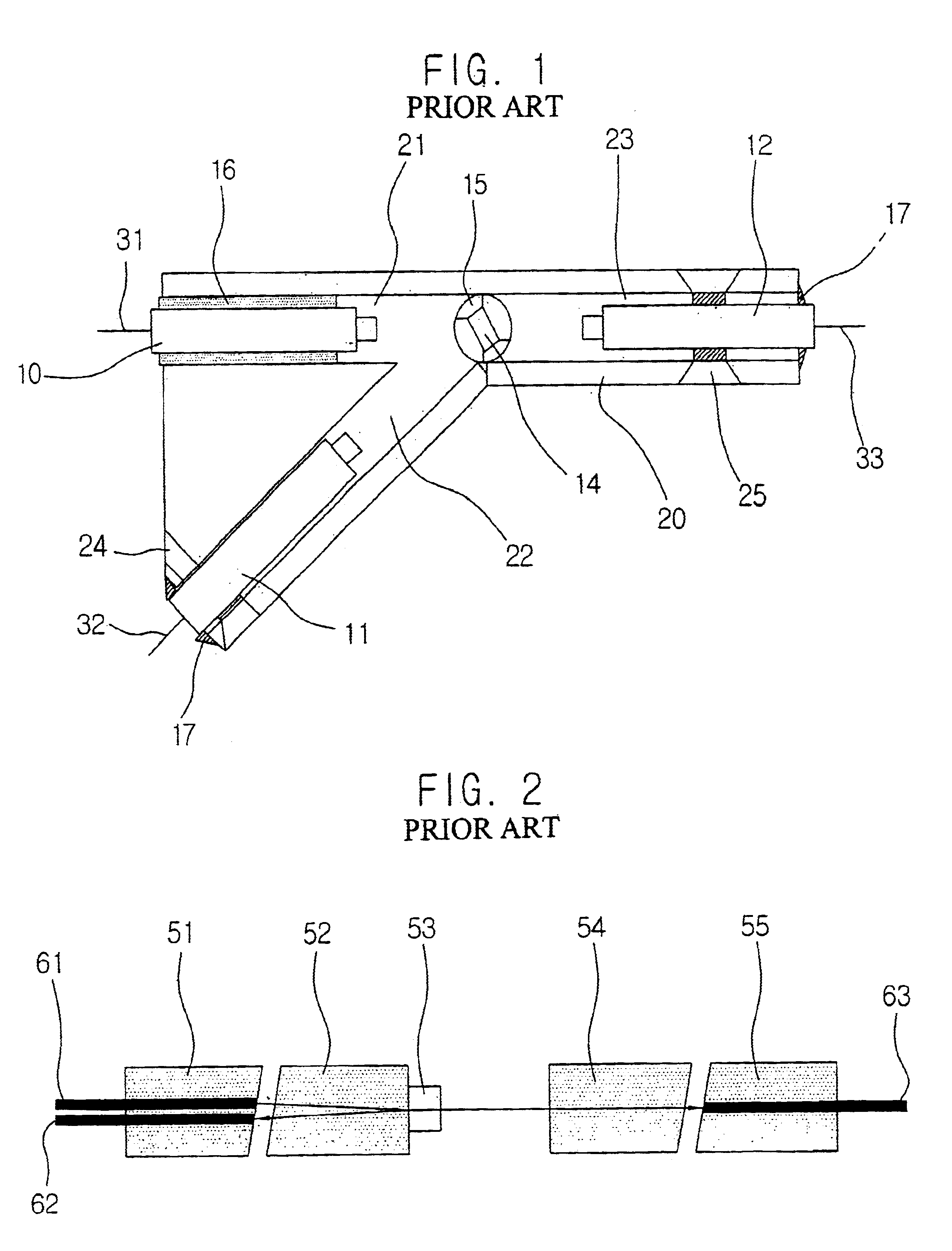
The conventional WDM has a disadvantage in that the packaging size increases upon packaging thereof.
Further, since the solder is injected through the holes formed in the outer housing to fix the collimators to the outer housing, the injection of the solder through the holes causes thermal deformation of the entire part due to a long heating time, thereby lowering the optical characteristics.
In addition, in case the collimator is fixed to the outer housing by applying the epoxy, it is weak in the fixing strength and vulnerable to thermal deformation.
Thus, there is a disadvantage of the deterioration of reliability.
In case of packaging such an optical filter part for optical communication, since the filter and the green lens are bonded directly to each other by means of epoxy, there is a disadvantage in that the reliability becomes lowered depending on temperature.
Since the thermosetting epoxy for use in fixing a single core collimator to an outer housing is cured by means of heating in a chamber, there is another disadvantage in that the optical part must be remounted on a piece of automation equipment to align the optical filter with the single core collimator as a post-process after the curing process.
Therefore, when the manufacture of the optical filter part is automated, it is impossible to continuously carry out operations, and a semi-automation process requiring workers must be performed.
Consequently, since workers should be involved upon construction of the semi-automation process, this causes a problem in that production costs of parts are increased.

Method used


Image

  • Method of packaging optical parts for optical communication
  • Method of packaging optical parts for optical communication
  • Method of packaging optical parts for optical communication

Examples


Embodiment Construction

[0041]Hereinafter, preferred embodiments of the present invention will be described in detail with reference to the accompanying drawings.

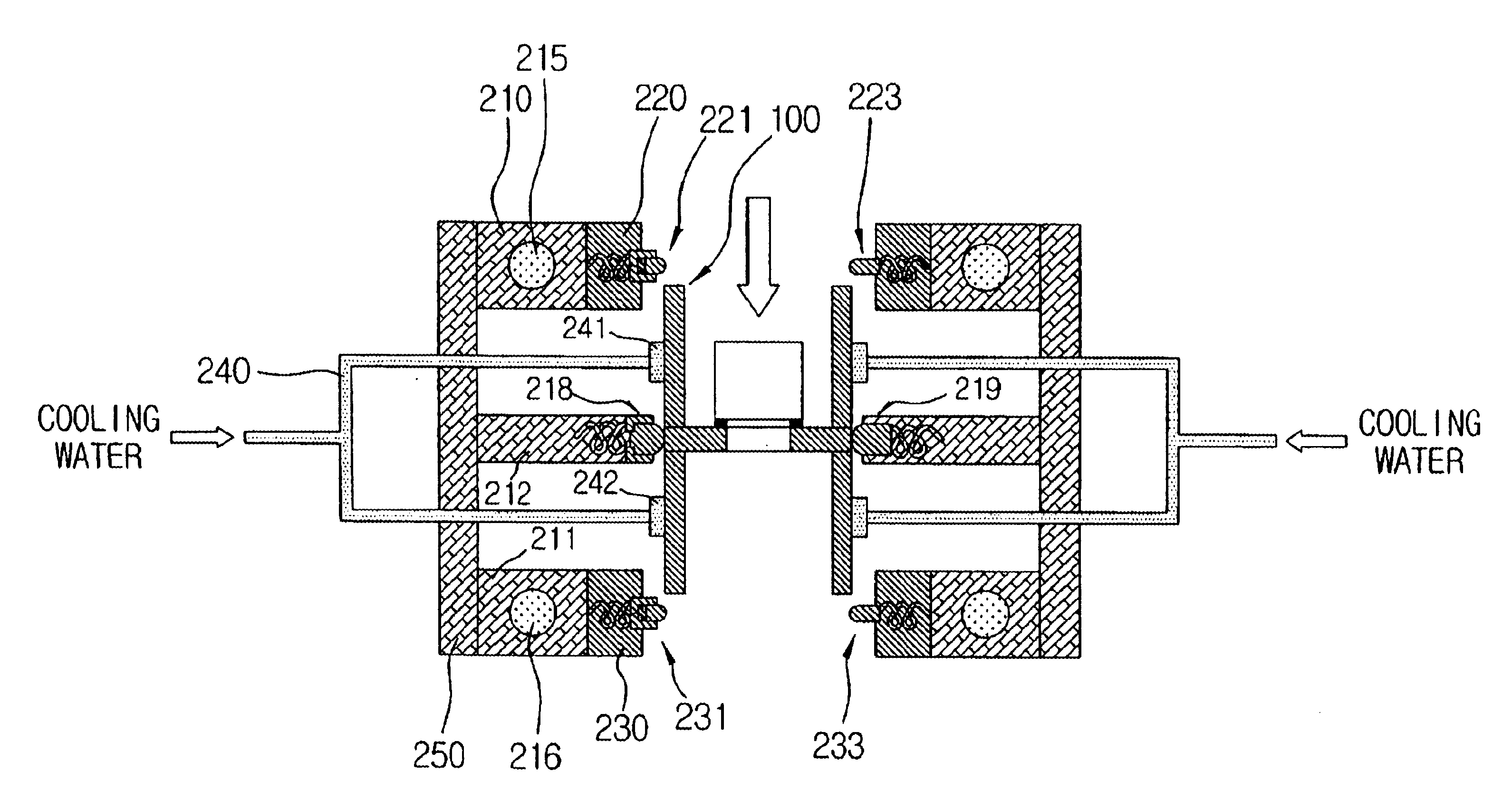
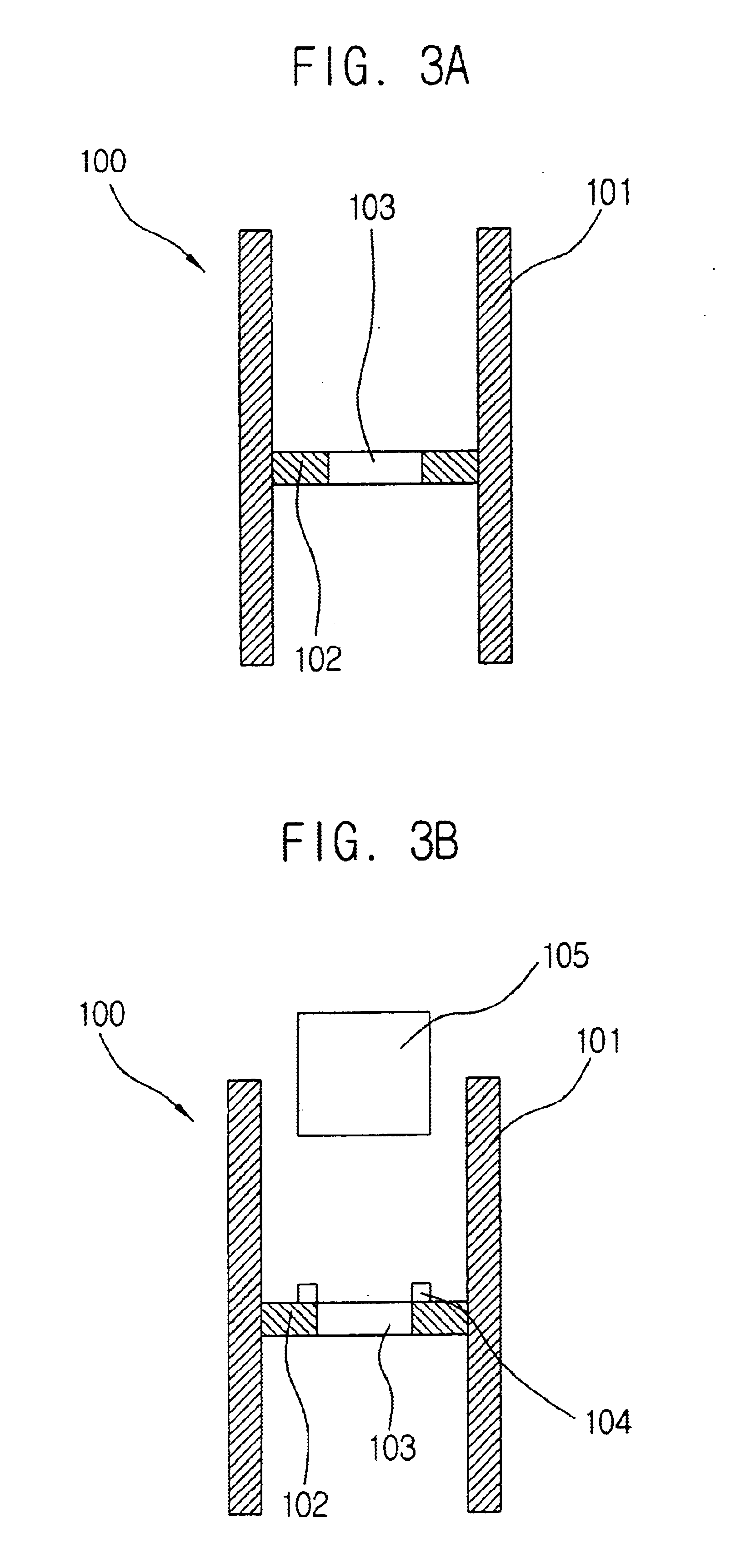
[0042]FIGS. 3a and 3b are sectional views illustrating a process for coupling an optical filter with a filter holder according to the present invention. First, a filter holder 100 that comprises a hollow tubular body 101 and a seating portion 102 is prepared (see FIG. 3a). The filter holder 100 has cylindrical inner and outer surfaces, and top and bottom faces that are open and communicate with each other. The seating portion 102 is formed to be in close contact with the inner surface of the tubular body 101 and has a hole 103 formed in the center thereof. Thermosetting epoxy 104 is applied around the hole 103 formed in the seating portion 102 of the filter holder 100, and an optical filter 105 is then pressed against the thermosetting epoxy 104 applied to the top of the seating portion 102 to be bonded thereto (see FIG. 3b).

[0043]Then, the thermo...


PUM


Abstract

The present invention relates to a method of packaging optical parts for optical communication. According to the method of the present invention, there are advantages in that a packaging process for optical parts is automated to improve productivity and to obtain price competitiveness and uniformity of quality, and a high frequency heater for locally transferring heat to only a solder preform is used to minimize thermal deformation of areas except a soldering area, thereby achieving highly reliable packaging of the optical parts.

Description

BACKGROUND OF THE INVENTION[0001]1. Field of the Invention[0002]The present invention relates to a method of packaging optical parts for optical communication, and more particularly, to a method of packaging optical parts for optical communication, wherein a packaging process for optical parts is automated to improve productivity and to obtain price competitiveness and uniformity of quality, and a high frequency heater for locally transferring heat to only a solder preform is used to minimize thermal deformation of areas except a soldering area, thereby achieving highly reliable packaging of the optical parts.[0003]2. Description of the Prior Art[0004]Recently, as the information and communication technology has been developed rapidly, high-speed communication networks are established between local areas and between countries and a great amount of data are transmitted / received at a high rate therebetween. In long-distance communication and local area communication, an optical fiber ...

Claims


Application Information

Patent Timeline
IPC IPC(8): G02B6/32G02B6/34G02B6/42
CPCG02B6/2937G02B6/327G02B6/29398G02B6/42
Inventor LEE, HYUNG MANIM, YOUNG MINKIM, MYUNG JINKIM, HWE KYUNGKIM, YOUNG IL
Owner KOREA ELECTRONICS TECH INST
Learn More