Data transmission across asynchronous clock domains

a data transmission and clock domain technology, applied in multiplex communication, generating/distributing signals, instruments, etc., can solve the problems of increasing the latency of moving data and related control information from the host, the internal control circuitry of the respective memory board, and the source of potential unreliable processing behaviors

Active Publication Date: 2005-06-21
EMC IP HLDG CO LLC
View PDF13 Cites 45 Cited by
  • Summary
  • Abstract
  • Description
  • Claims
  • Application Information

AI Technical Summary

Benefits of technology

[0016]Advantageously, it has been found that by practicing this embodiment of the present invention in a shared cache memory resource of a network data storage system, it is possible to eliminate the need to use, in the respective memory boards of the shared cache memory resource, the aforesaid type of discrete IC chips that comprise the aforesaid type of conventional serial-to-parallel converter circuitry (and, in particular, the elastic FIFO memories used in su

Problems solved by technology

In order to try to prevent the FIFO memory from filling too quickly (and thereby possibly overwriting valid user data that has yet to be retrieved from the FIFO by the memory board's control circuitry), or emptying too quickly (and thereby possibly causing the same user data to be retrieved twice by the control circuitry), a relatively complex, “elastic” FIFO buffer memory may be employed as the FIFO memory in the serial-to-parallel converter circuitry.
The elastic FIFO/buffer memories used in such conventional serial-to-parallel converter circuitry typically comprise relatively complex circuitry, may require undesirably large amounts of processing overhead to carry out their respective operations, and may introduce sources of potential unreliable processing behaviors into t

Method used


Image

  • Data transmission across asynchronous clock domains
  • Data transmission across asynchronous clock domains
  • Data transmission across asynchronous clock domains

Examples


Embodiment Construction

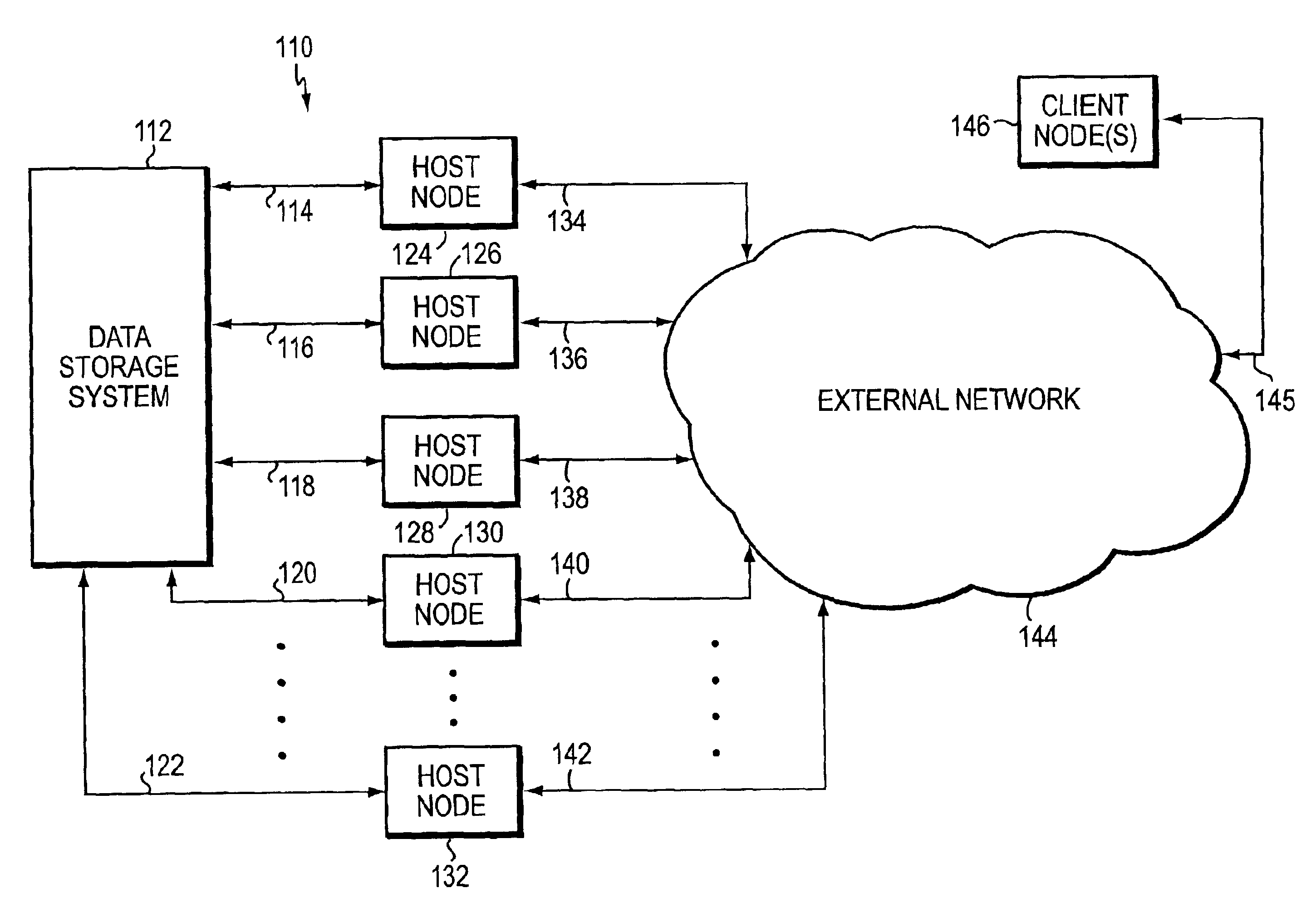
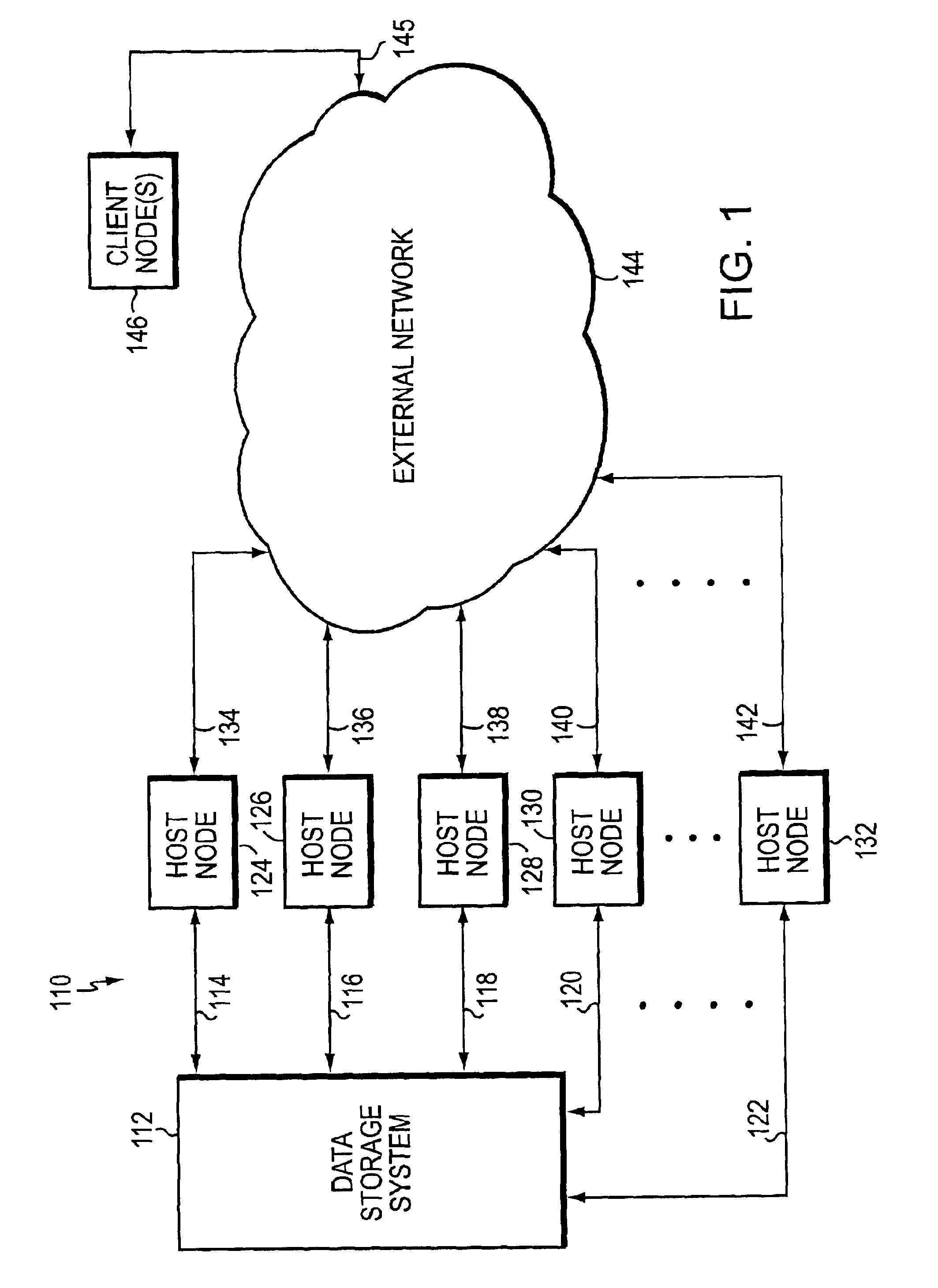
[0023]Turning now to the Figures, illustrative embodiments of the present invention will be described. FIG. 1 is a high-level block diagram illustrating a data storage network 110 that includes a network data storage system 112 wherein one embodiment of the subject invention may be practiced to advantage. System 112 is coupled via communication links 114, 116, 118, 120, . . . 122 to respective host computer nodes 124, 126, 128, 130, . . . 132. Each of the communication links 114, 116, 118, 120, . . . 122 may be configured for communications involving a respective conventional network communication protocol (e.g., FC, ESCON, SCSI, Fibre Connectivity, Gigabit Ethernet, etc.). Host nodes 124, 126, 128, 130, . . . 132 are also coupled via additional respective conventional network communication links 134, 136, 138, 140, . . . 142 to an external network 144. Network 144 may comprise one or more Transmission Control Protocol / Internet Protocol (TCP / IP)-based and / or Ethernet-based local are...


PUM


Abstract

In one embodiment of the present invention, a system is provided for use in transmitting data and related control information from a first clock domain to a second clock domain. The system may include a first logic section that may generate respective identification information that may be used to identify respective types of information represented by respective data and related control information. The system may also include memory that may receive and store, at a first clock rate used in the first clock domain, the respective data and related control information. The memory also may store, in association with the respective data and related control information, the respective identification information. The memory may be configured to permit the retrieval, at a second clock rate used in the second clock domain, of the respective data, the respective related control information, and the respective identification information stored in the memory.

Description

FILED OF THE INVENTION[0001]The present invention relates to a novel and non-obvious technique that may be used to facilitate transmission of data across asynchronous clock domains.BACKGROUND OF THE INVENTION[0002]Network computer systems generally include a plurality of geographically separated or distributed computer nodes that are configured to communicate with each other via, and are interconnected by, one or more network communications media. One conventional type of network computer system includes a network storage subsystem that is configured to provide a centralized location in the network at which to store, and from which to retrieve data. Advantageously, by using such a storage subsystem in the network, many of the network's data storage management and control functions may be centralized at the subsystem, instead of being distributed among the network nodes.[0003]One type of conventional network storage subsystem, manufactured and sold by the Assignee of the subject appl...

Claims


Application Information

Patent Timeline
IPC IPC(8): G06F13/00G06F12/00G06F3/06H04L7/02
CPCG06F3/061G06F3/0656H04L7/005H04L7/02G06F3/067
Inventor MACLELLAN, CHRISTOPHER S.ROBIDOUX, GREGORY S.WALTON, JOHN K.CHILTON, KENDELL A.
Owner EMC IP HLDG CO LLC
Why Eureka
Try Eureka