Production method of a sequentially joined-segment stator coil of a rotary electrical machine

a production method and stator coil technology, applied in forging/hammering/hammering machines, magnetic bodies, forging/hammering/pressing apparatuses, etc., can solve problems such as damage to the insulating coating on the tip, and achieve the effect of reducing the variation of resistan

Inactive Publication Date: 2005-06-28
DENSO CORP
View PDF16 Cites 17 Cited by
  • Summary
  • Abstract
  • Description
  • Claims
  • Application Information

AI Technical Summary

Benefits of technology

[0033]In the above described sequentially joined-segment stator coil of the invention, the slots are broken down into same phase slot groups each of which has placed therein the conductor portions of the segments to which the same phase voltage is applied. The slots in each of the same phase slot groups are arrayed adjacent to each other in the circumferential direction of the stator core. The partial phase windings arrayed in the radius direction of the stator core within each of the slots of each of the same phase slot groups are joined in series to form a series-connected phase coil circuit. The series-connected phase coil circuits placed respectively within the slots of each of the same phase slot groups are joined in parallel to form each of the phase coils. The parallel joint results in decreases in variation in resistance among the series-connected phase coil circuits and in electrical current flowing therethrough.

Problems solved by technology

The tension stress acts between the tip of the head of each conductor segment and a side portion of the chamfered surface of the tine abutting the tip, which causes the damage to the insulating coating on the tip.

Method used


Image

  • Production method of a sequentially joined-segment stator coil of a rotary electrical machine
  • Production method of a sequentially joined-segment stator coil of a rotary electrical machine
  • Production method of a sequentially joined-segment stator coil of a rotary electrical machine

Examples


Embodiment Construction

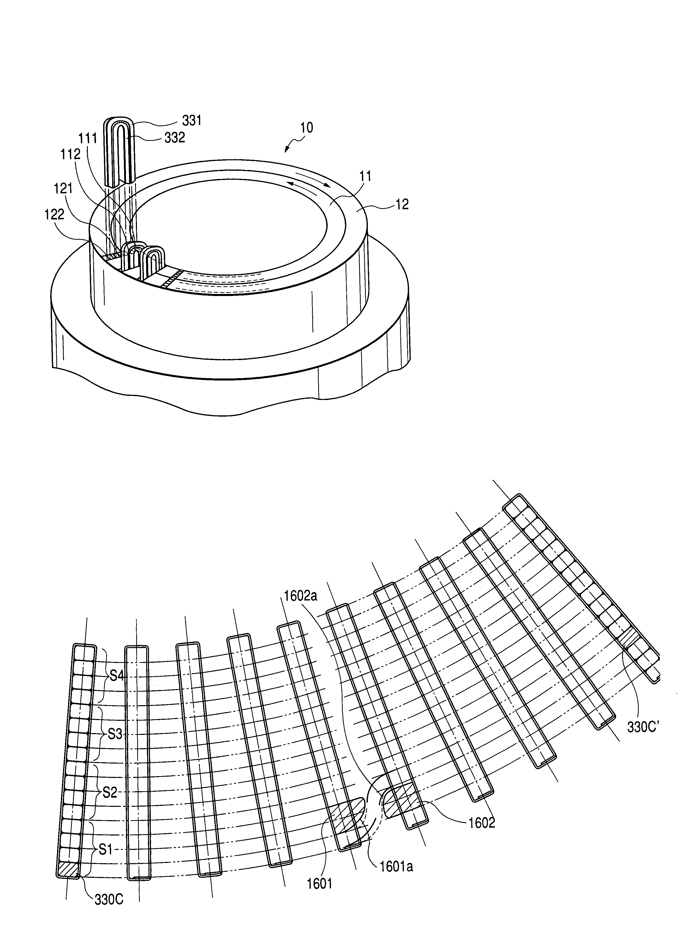
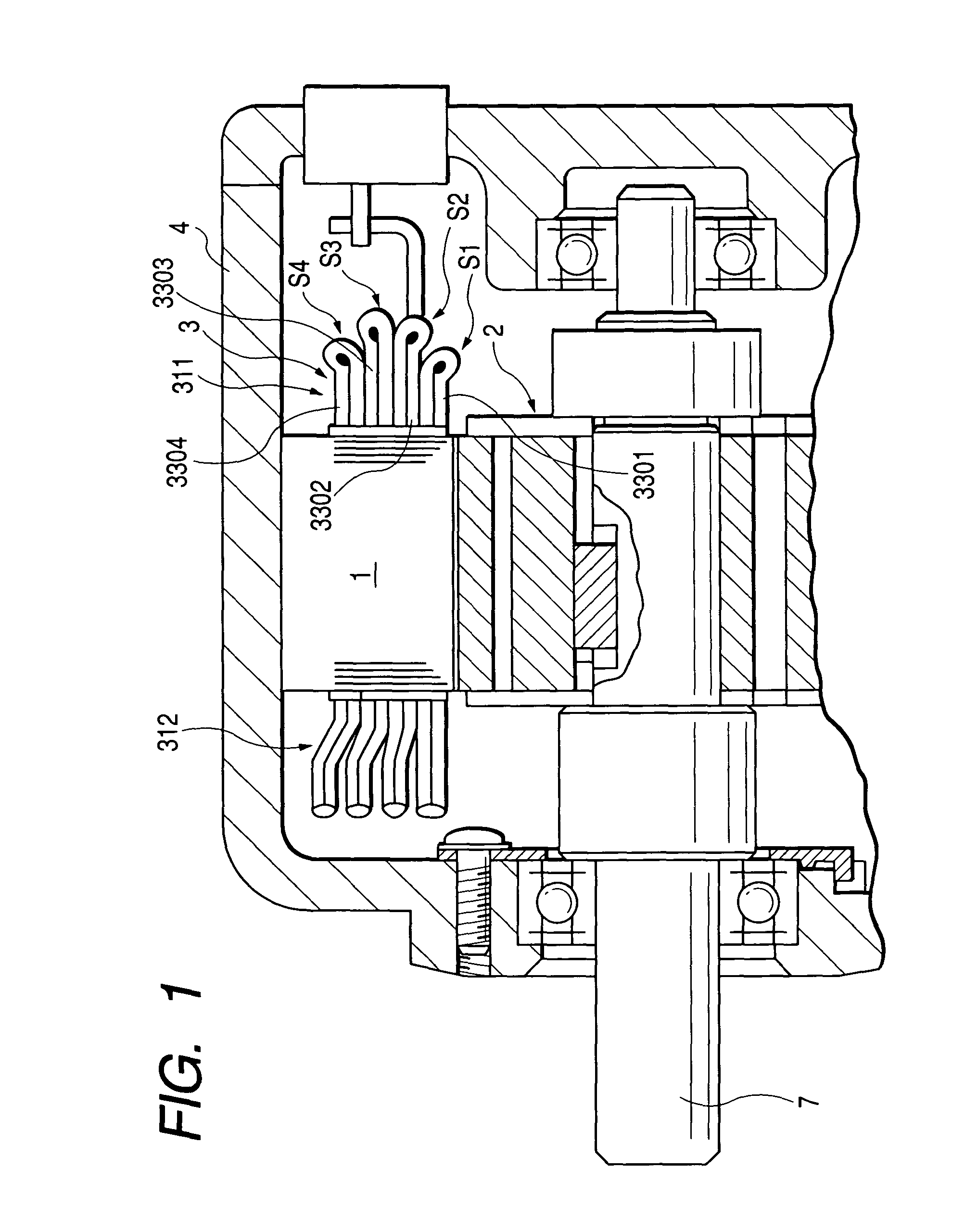
[0049]Referring to the drawings, wherein like reference numbers refer to like parts in several views, particularly to FIG. 1, there is shown a high-voltage rotary electrical machine for automotive vehicles according to the invention which is equipped with a sequentially joined-segment stator coil.

[0050]The rotary electrical machine may be used as a drive motor designed to produce power to drive an automotive vehicle such as an electric automobile. The rotary electrical machine consists essentially of a stator core 1, a rotor 2, a stator coil 3, a housing 4, and a rotary shaft 7. The stator core 1 is fixed to an inner peripheral wall of the housing 4. The stator coil 3 is wound in slots formed in the stator core 1. The rotor 2 is of an IPM type which is installed on the rotary shaft 7 supported rotatably by the housing 4 through bearings. The rotor 2 is disposed within the stator core 1. The stator coil 3 is implemented by a three-phase armature winding and supplied with power from a...


PUM

PropertyMeasurementUnit
angleaaaaaaaaaa
radius of curvatureaaaaaaaaaa
degree of electrical insulationaaaaaaaaaa

Abstract

A production method of a polyphase sequentially joined-segment coil of a rotary electric machine and a product produced by the same are provided. A production machine includes pairs of tines working to catch heads of conductor segments when they are twisted using rings. The tines are designed to be rotatable about an axis of the rings following rotation of the rings to absorb stress acting on insulating coating on the heads of the segments to minimize rubbing of the insulating coatings, thereby ensuring a desired degree of electrical insulation of the stator coil.

Description

CROSS-REFERENCE TO RELATED APPLICATION[0001]The present application claims the benefit of Japanese application, JP 2002-184929 filed on Jun. 25, 2002.BACKGROUND OF THE INVENTION[0002]1. Technical Field of the Invention[0003]The present invention relates generally to a sequentially joined-segment coil of a rotary electric machine and a production method thereof which ensures a high degree of electrical insulation.[0004]2. Background Art[0005]Sequentially joined-segment stator coils have been proposed which are made by conductor segments inserted in slots in a stator core whose ends are joined in sequence. For instance, Japanese Patent No. 3118837, assigned to the same assignee as that of this application, discloses a production method of joining U-shaped conductor segments in sequence to make a stator coil.[0006]The sequentially joined segment stator coil, as taught in the above patents, is made by inserting a pair of legs of each conductor segment into two of slots of a core located...

Claims


Application Information

Patent Timeline
Patent Type & Authority Patents(United States)
IPC IPC(8): H02K15/04H02K3/04H02K15/06H02K15/085
CPCH02K15/0428H02K15/064Y10T29/49009Y10T29/49011Y10T29/49012Y10T29/53143Y10T29/49071
Inventor GOROHATA, TETSUYAKAMAKURA, YOUICHIHIRANO, HITOSHI
Owner DENSO CORP
Why Eureka
Try Eureka