Rankine cycle device of internal combustion engine

a technology of internal combustion engine and cycle device, which is applied in the direction of machines/engines, positive displacement liquid engines, mechanical equipment, etc., can solve the problems of retardation of catalyst activation and difficulty in effective operation of rankine cycle system, and achieve the effect of promoting the activation of catalyst in the exhaust emission control device and efficient recovery of waste hea

Inactive Publication Date: 2005-06-28
HONDA MOTOR CO LTD
View PDF10 Cites 79 Cited by
  • Summary
  • Abstract
  • Description
  • Claims
  • Application Information

AI Technical Summary

Benefits of technology

[0005]The present invention has been accomplished with the above-described circumstances in view, and it is an object of the present invention to ensure that the efficiency of recovery of a waste heat from an internal combustion engine by a Rankine cycle system is increased to the maximum, and the activation of a catalyst in an exhaust emission control device is promoted.

Problems solved by technology

However, if an evaporator in a Rankine cycle system is disposed at a location upstream of the exhaust emission control device, the following problem is encountered: the exhaust gas is robbed of its heat by the evaporator and hence, the activation of the catalyst is retarded.
For this reason, the downstream evaporator cannot generate a sufficient amount of vapor and thus, it is difficult to effectively operate the Rankine cycle system.

Method used


Image

  • Rankine cycle device of internal combustion engine
  • Rankine cycle device of internal combustion engine
  • Rankine cycle device of internal combustion engine

Examples


Embodiment Construction

[0025]An embodiment of the present invention will now be described with reference to FIGS. 1 to 12.

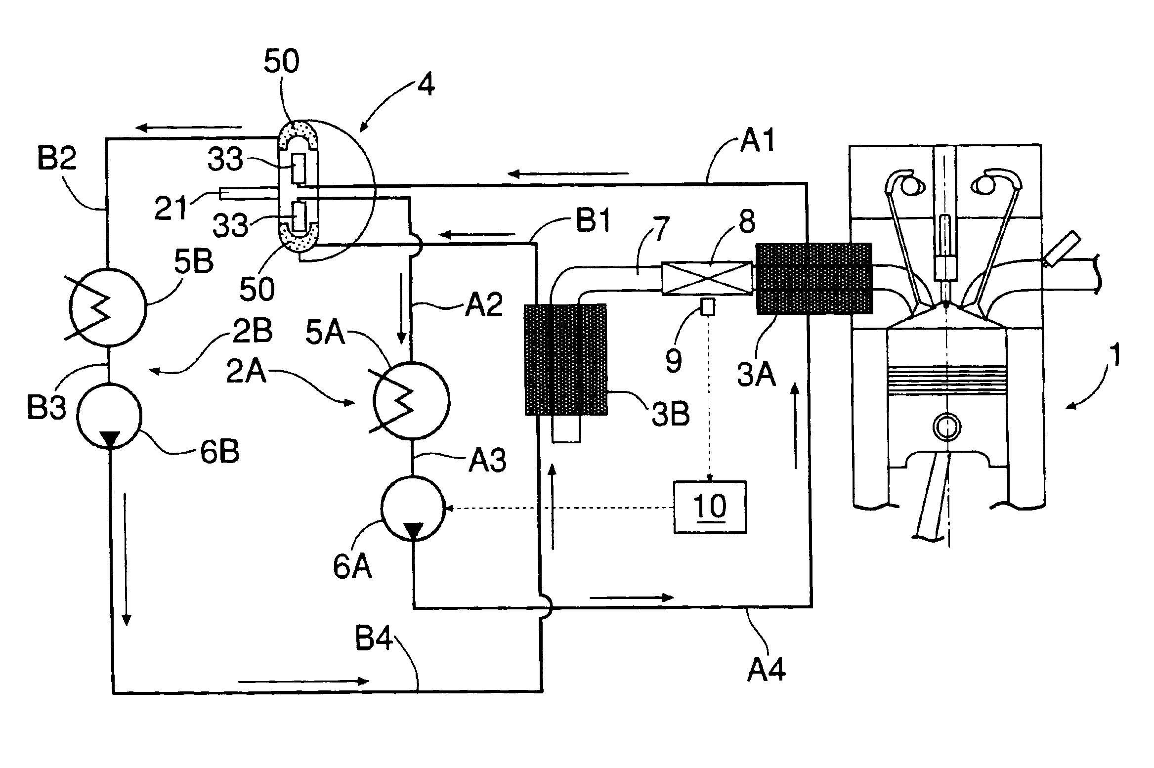
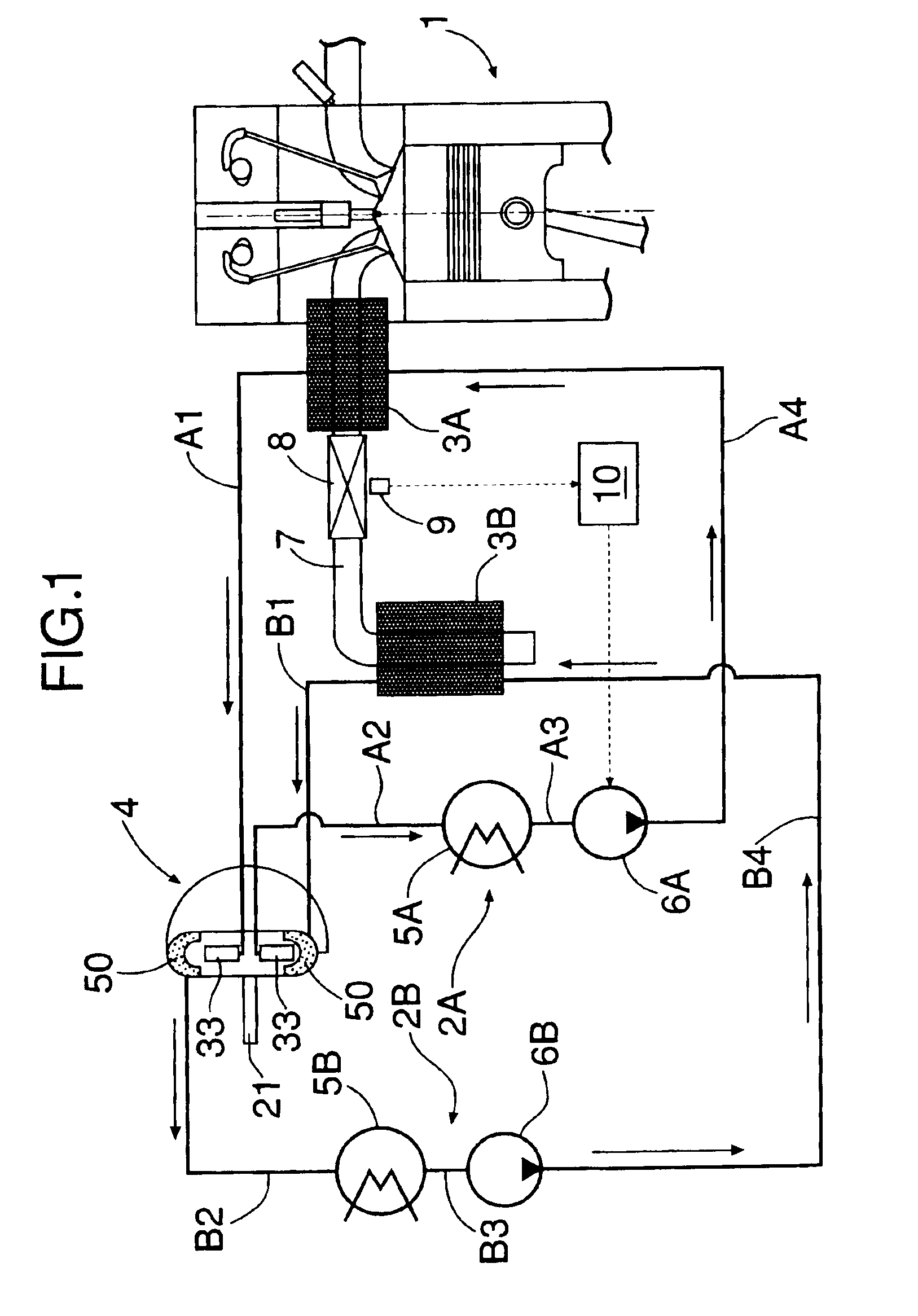
[0026]Referring to FIG. 1, a Rankine cycle system using an exhaust gas from an internal combustion engine 1 as a heat source is comprised of a first Rankine cycle 2A and a second Rankine cycle 2B using working media independent from each other. An exhaust emission control device 8 of a ternary catalyst type is mounted in an exhaust passage 7 for the internal combustion engine 1; and a first evaporator 3A is mounted at a location upstream of the exhaust emission control device 8, and a second evaporator 3B is mounted at a location downstream of the exhaust emission control device 8.

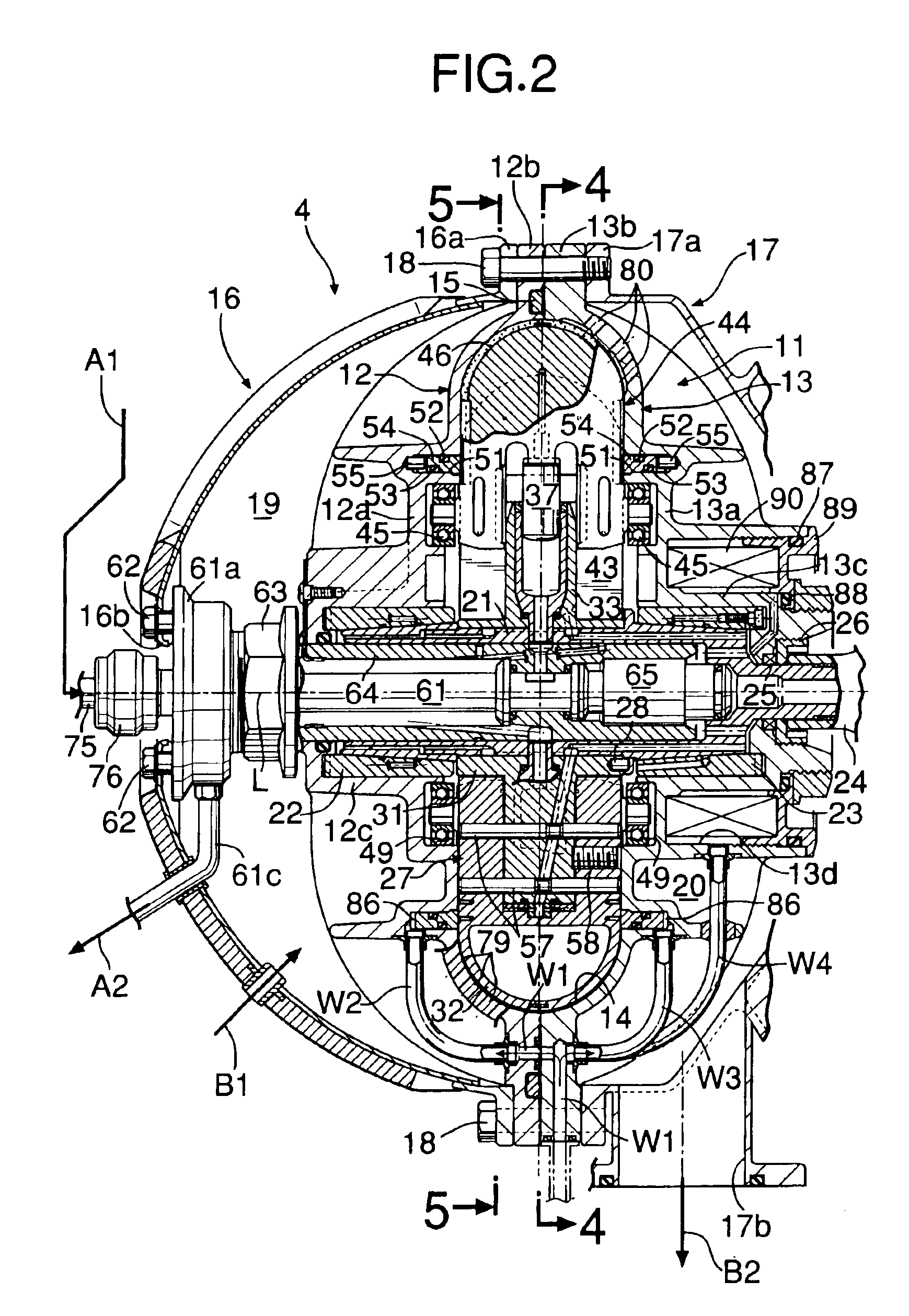
[0027]The first Rankine cycle 2A includes the first evaporator 3A for gasifying a first working medium having a high boiling point (water in the embodiment) by heat of the exhaust gas to generate vapor in a high-temperature and a high-pressure state, an expander 4 for generating an output by th expansion of t...


PUM


Abstract

A Rankine cycle system includes a first Rankine cycle (2A) operated by a first working medium and a second Rankine cycle (2B) operated by a second working medium. The first Rankine cycle (2A) is constituted from an evaporator (3A), an expander (4), a condenser (5A) and a supply pump (6A), and the second Rankine cycle (2B) is constituted from an evaporator (3B), the expander (4), a condenser (5B) and a supply pump (6c). The evaporator (3A) in the first Rankine cycle (2A) and the evaporator (3B) in the second Rankine cycle (2B) are disposed at locations upstream and downstream of an exhaust emission control device (8) mounted in an exhaust passage (7) for the internal combustion engine (1). The first working medium has a boiling point higher than that of the second working medium, and the capacity of the pump (6A) in at least the first Rankine cycle (2A) is variable. Thus, the efficiency of recovery of a waste heat from the internal combustion engine by the Rankine cycle system can be enhanced to the maximum, and the activation of the exhaust emission control device can be promoted.

Description

[0001]This application is the national phase under 35 U.S.C. § 371 of PCT International Application No. PCT / JP01 / 08825 which has an International filing date of Oct. 5, 2001, which designated the United States of America.FIELD OF THE INVENTION[0002]The present invention relates to a Rankine cycle system for an internal combustion engine, including a first Rankine cycle operated by a first working medium and a second Rankine cycle operated by a second working medium.BACKGROUND ART[0003]There are waste-heat recovery systems known from Japanese Patent Application Laid-open Nos.60-93110 and 8-68318, each of which includes heat exchangers mounted at locations upstream and downstream of an exhaust emission control device mounted in an exhaust passage for an internal combustion engine, so that water as a working medium is supplied to the heat exchangers where it is subjected to a heat exchange with an exhaust gas. There are also Rankine cycle systems known from Japanese Patent No.2650660, ...

Claims


Application Information

Patent Timeline
Patent Type & Authority Patents(United States)
IPC IPC(8): F01B17/04F01K23/10F01B17/00F01N3/28F01N3/20F01K23/06F01N5/00F01N5/02F02G5/00F02G1/00F02G1/04F02G5/04F02B53/00F02G5/02F04B41/06
CPCF01B17/04F01K23/065F01K23/106F01N3/2006F01N3/2882F02G1/04F02G5/04F01N5/02Y02T10/26Y02T10/16Y02T10/166Y02T10/12
Inventor MINEMI, MASAHIKOMIURA, HIROYUKIYOSHIDA, KAZUOMIYAO, MASAKATSU
Owner HONDA MOTOR CO LTD
Why Eureka
Try Eureka