Control arm system for steering bogie wheels and axles

a control arm and steering wheel technology, applied in passenger carriages, railway components, underframes, etc., can solve the problems of frame bogies, general inability to manufacture, minimum wear of wheel flanges and rail heads, etc., and achieve the effect of increasing life and less wear

Inactive Publication Date: 2005-06-28
BESCO AMERICA
View PDF11 Cites 18 Cited by
  • Summary
  • Abstract
  • Description
  • Claims
  • Application Information

AI Technical Summary

Benefits of technology

[0027]Therefore the main object of the present invention is to propose an improved bogie whi

Problems solved by technology

There are disadvantages associated with the existing system of ‘H’ frame bogies.
One of the main disadvantages associated with the present system of conventional ‘H’ frame bogies is that when the wheels run on a pair of straight rail tracks, when there is a perfect alignment between the wheel flange and rail head and the wear of the wheel flange and rail head may be minimum.
This in general is not practicable during manufacture.
When tolerances are applied the trueness of geometry is affected and wear propensity increases.
Due to continuous rubbing of the wheel flange on rail head both wears very fast.
Since neither the speed nor the haulage loads could be reduced for economic reasons, this wheel wears can not be avoided in conventional bogie wheels and rail heads.
Another disadvantage associated with the present system of conventional ‘H’ frame bogies is that the bogie frame oscillates continuously and the rubbing faces wear rapidly causing increase in clearances between the ‘H’ frame and axle boxes of the wheels.
Even when the frame is new, due to initial clearances, the conventional bogie tends to become unstable exhibiting a behaviour called ‘hunting’ at speeds above 50/55 k.m.p.h on straight track.
Yet another disadvantage associated with the present conventional ‘H’ frame bogies is that the front pair of wheels and the rear pair of wheels being independent of each other and having clearances to play never negotiate the track rail tangentially.
In view of all above disadvantagaes, a fast moving bogie either on Tangent Track or when trying to negotiate a curved track will have its alignment lost because of lozenging effect of ‘H’ frame.
Even in a bogie where the wheel

Method used


Image

  • Control arm system for steering bogie wheels and axles
  • Control arm system for steering bogie wheels and axles
  • Control arm system for steering bogie wheels and axles

Examples


Embodiment Construction

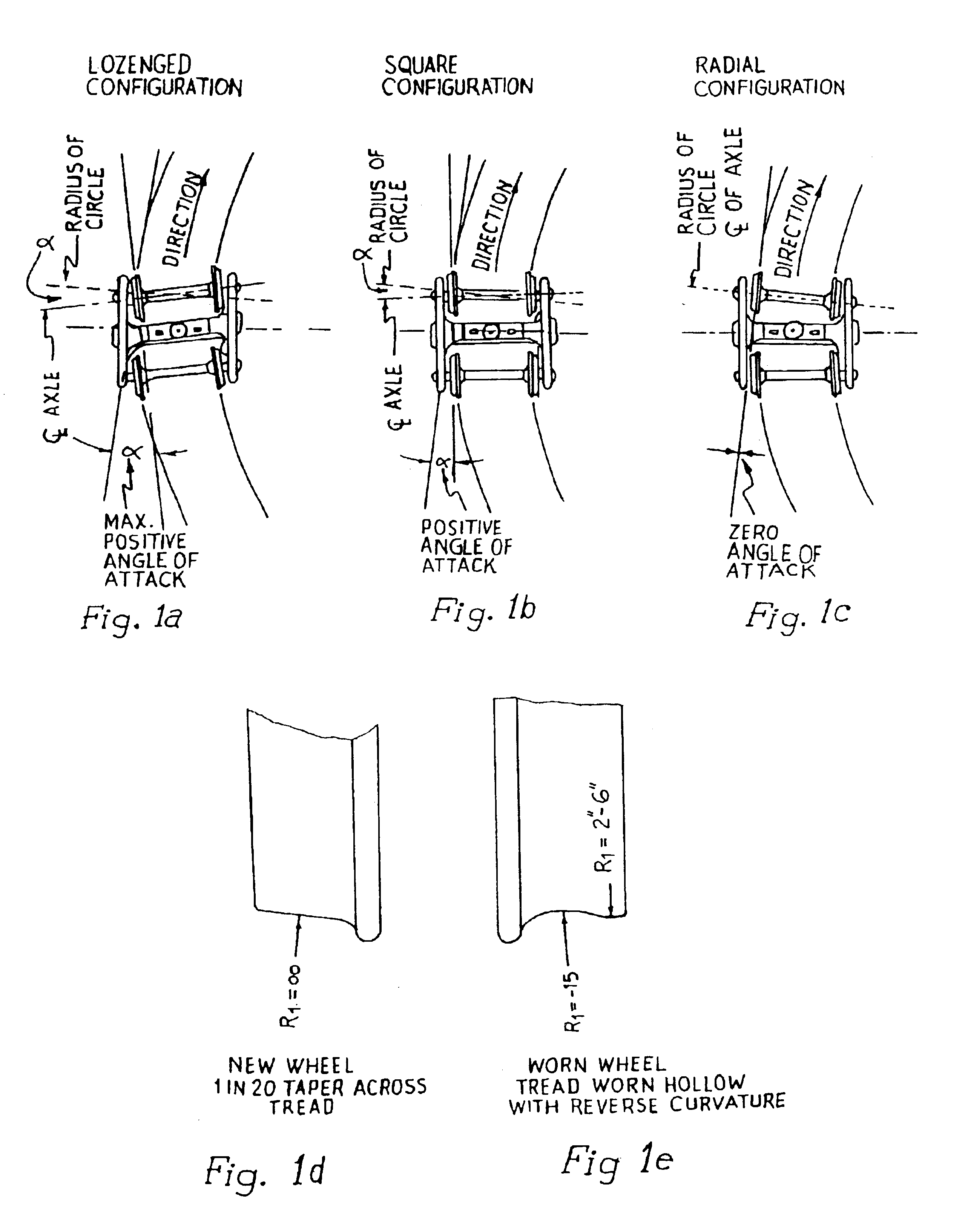
[0048]FIGS. 1a, 1b, 1c illustrates three different exemplary angles of attack which has been described earlier. FIGS. 1d and 1e illustrate tread profile when new and after it has been worn out. The object of the invention is to propose a bogie which improves the angle of attack during negotiating a curve. So worn out of the tread is minimised and the Wagon or freight car with the improved bogie can negotiate the curve at higher speed.

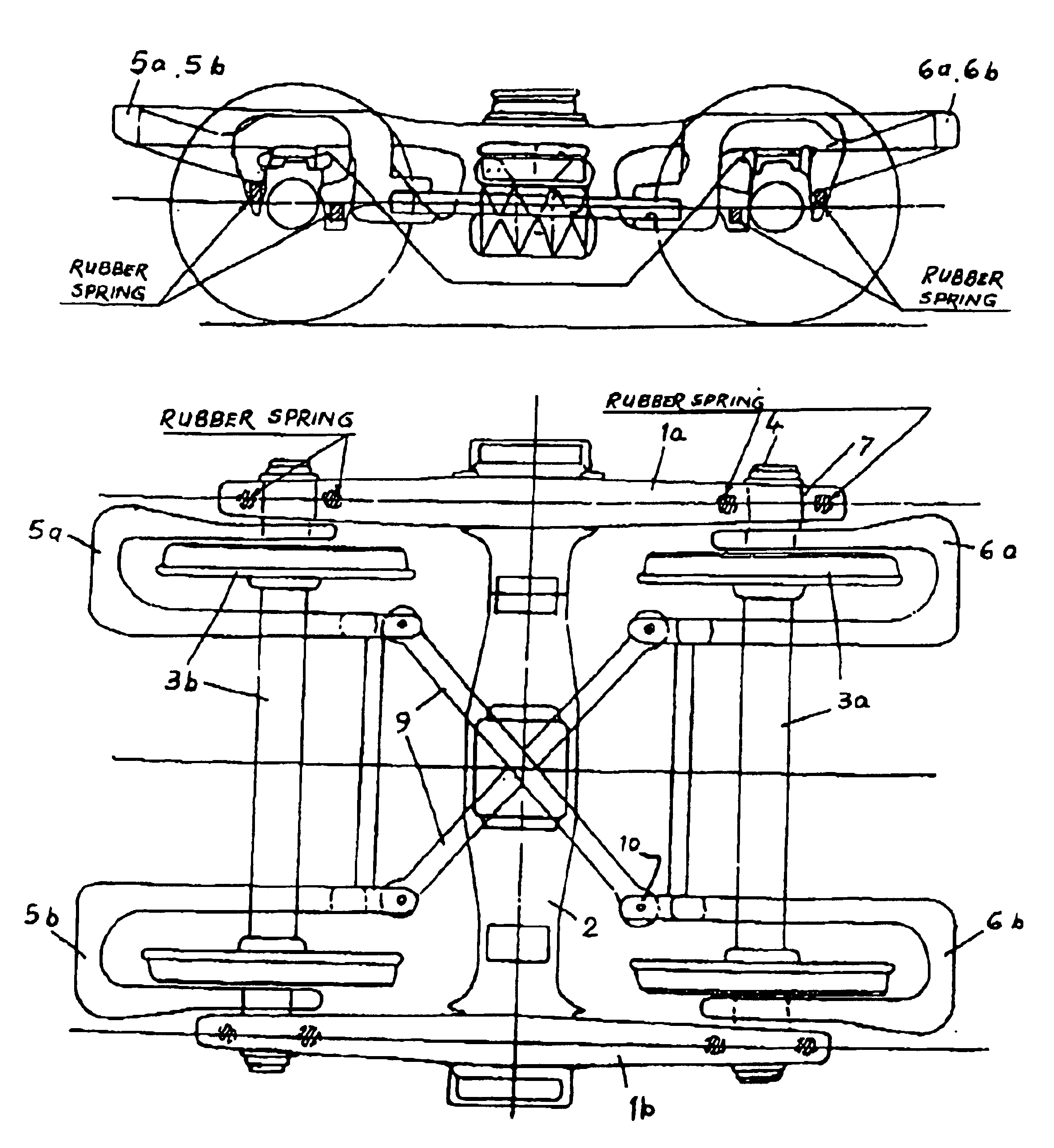
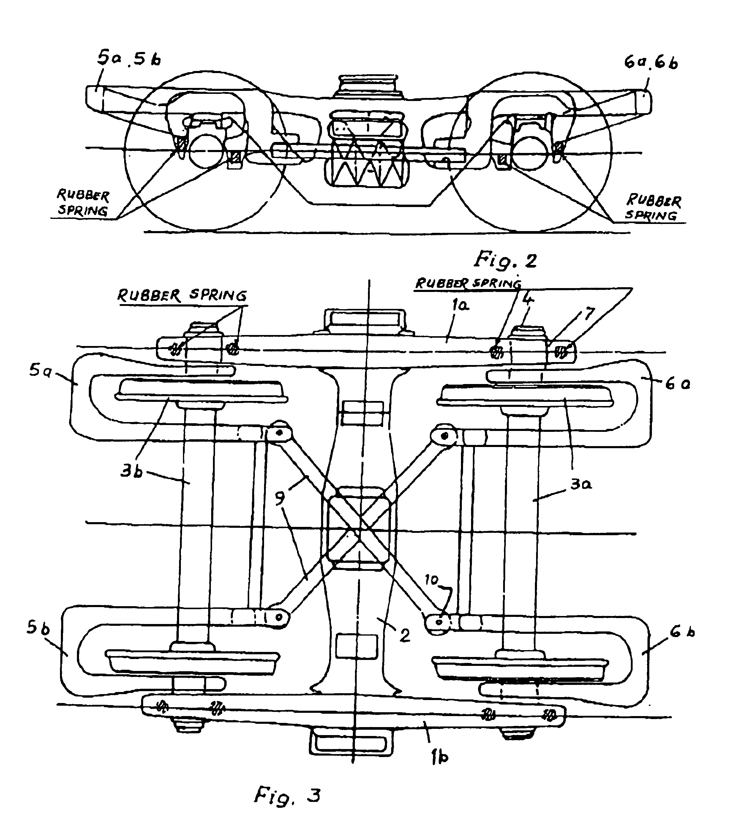
[0049]FIGS. 2 and 3 shows the improved bogie of our invention with out-board ‘C’ Arms and FIGS. 2A and 3A shows the improved bogie with in-board Arms.

[0050]The bogie primarily comprises of an ‘H’ frame formed by the bolster (2) and a pair of side frames (1a, 1b). The two side frames are mounted over the axle boxes (4) of the wheels and axles (3a, 3b). Two C-type arms, one for out-board application (5a, 6a; 5b, 6b) or for in-board application (5′a, 5′b; 6′a and (6′b) used in pair and comprises the control arms for each axle (3a, 3b).

[0051]The two pairs o...


PUM


Abstract

An improved bogie control arm for steering wheels and axles of bogies comprising of two pairs of C-type control arm made out of rolled steel channel section which has been flared by splitting the web and thereafter welding profile cut steel plates, two pairs of fabricated adapter is connected to said control arm by means of welding or rivetting, the fabricated adapter is provided with rubber spring as primary suspension, the two pairs of ‘C’-type control arms are connected to each other by means of cross struts and pins.

Description

FIELD OF INVENTION[0001]This invention relates to an outboard bogie control arm and an improved inboard bogie control arm for steering wheels and axles of bogies for Railway wagons and carriages.[0002]Cast steel bogies with three pieces ‘H’ frame comprising two side frames and a bolster connecting the side frames are very much in use throughout the world railways for carrying wagons with heavy freight and at high speed.BACKGROUND OF THE INVENTION[0003]This conventional bogie has two pairs of wheels with axles viz a front pair of wheels and a rear pair of wheels for facilitating running of the wagon on rails. The wheels are firmly fitted on axle which rotates together while running and are held in position by the ‘H’ frame at end of axles through boxes. It is the ‘H’ frame which plays a major part for the total behaviour of the bogie.[0004]There are disadvantages associated with the existing system of ‘H’ frame bogies.[0005]One of the main disadvantages associated with the present sy...

Claims


Application Information

Patent Timeline
IPC IPC(8): B61F5/38B61F5/00
CPCB61F5/38
Inventor KRISHNASWAMI, BALASUBRAMANYAN ANANTHANARAYANAN
Owner BESCO AMERICA
Why Eureka
Try Eureka