Method of supplying slurry and a slurry supply apparatus having a mixing unit at a point of use

Inactive Publication Date: 2005-06-28
SAMSUNG ELECTRONICS CO LTD
View PDF7 Cites 27 Cited by
  • Summary
  • Abstract
  • Description
  • Claims
  • Application Information

AI Technical Summary

Benefits of technology

[0011]In the embodiments of the present invention, a slurry mixing and dispensing system preferably comprises one or more elements for the storage, mixing, pumping, filtering, and routing of a mixture of polishing slurry for applications in a chemical mechanical polishing (CMP) apparatus. Primary features include 1) re-circulation loops for keeping a slurry solution in an agitated and suspended state, and 2) providing efficient mixing of chemical additives, such as time-sensitive curing chemi

Problems solved by technology

Disadvantageously, unless the slurries are kept in an agitated or suspension state, abrasive particles will precipitate out of the solution and solidify in interconnecting conduits of the delivery system.
Further, such precipitated particles flow out of the slurry supply apparatus in an irregular manner, thereby degrading the uniformity of the chemical mechanical polishing process.
As a result, it is difficult to supply slurry having a uniform concentration and uniform mixing ratio to the polishing pad and thus difficult to perform a uniform, reliable and stable CMP process.
Both of these approaches ha

Method used


Image

  • Method of supplying slurry and a slurry supply apparatus having a mixing unit at a point of use
  • Method of supplying slurry and a slurry supply apparatus having a mixing unit at a point of use
  • Method of supplying slurry and a slurry supply apparatus having a mixing unit at a point of use

Examples


Embodiment Construction

[0029]Korean Patent Application No. 2001-74547, filed on Nov. 28, 2001, and entitled “Slurry Supply Apparatus having a Mixing Unit at a Point of Use and a Slurry Storage Unit,” is incorporated by reference herein in its entirety.

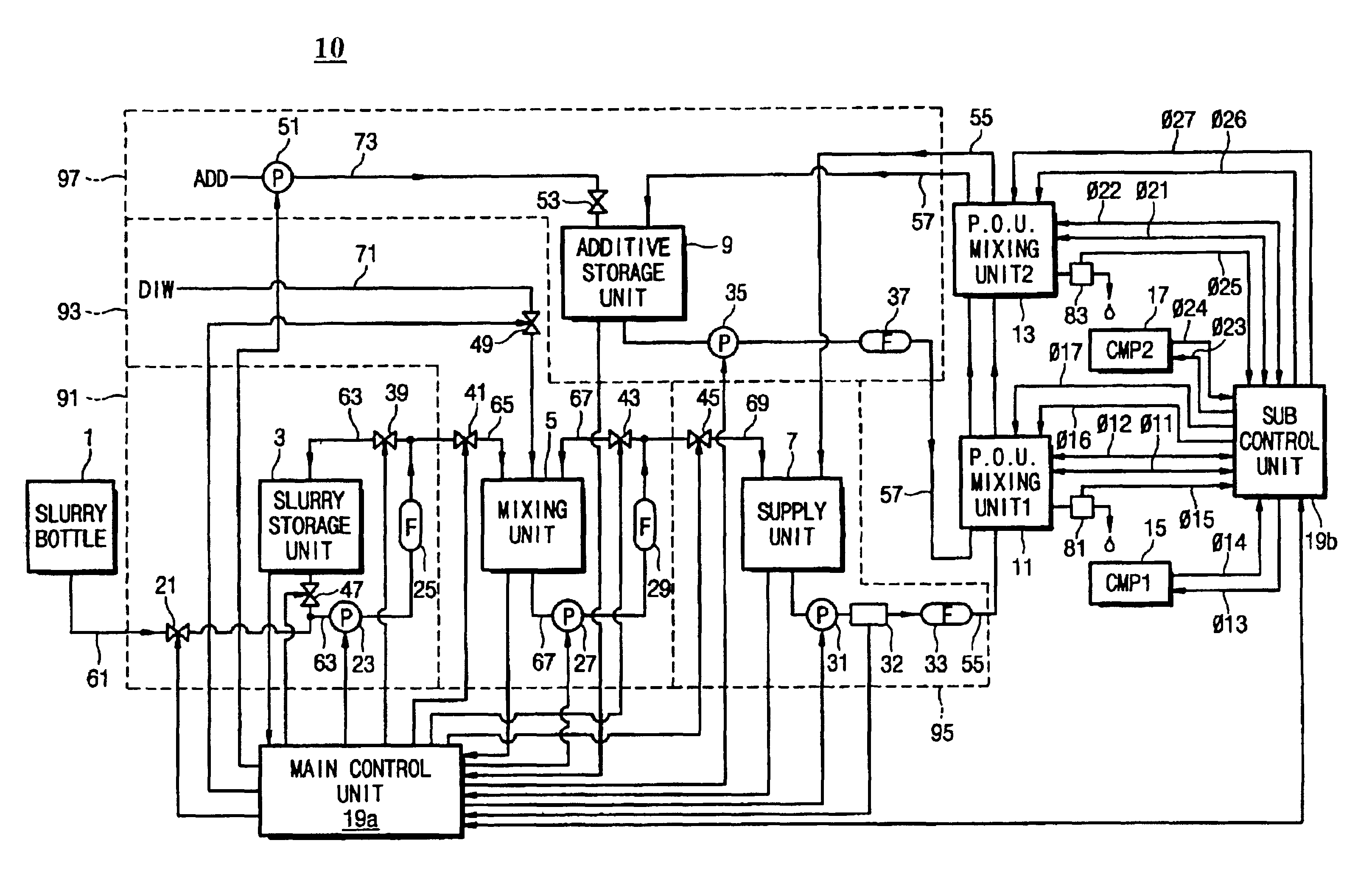
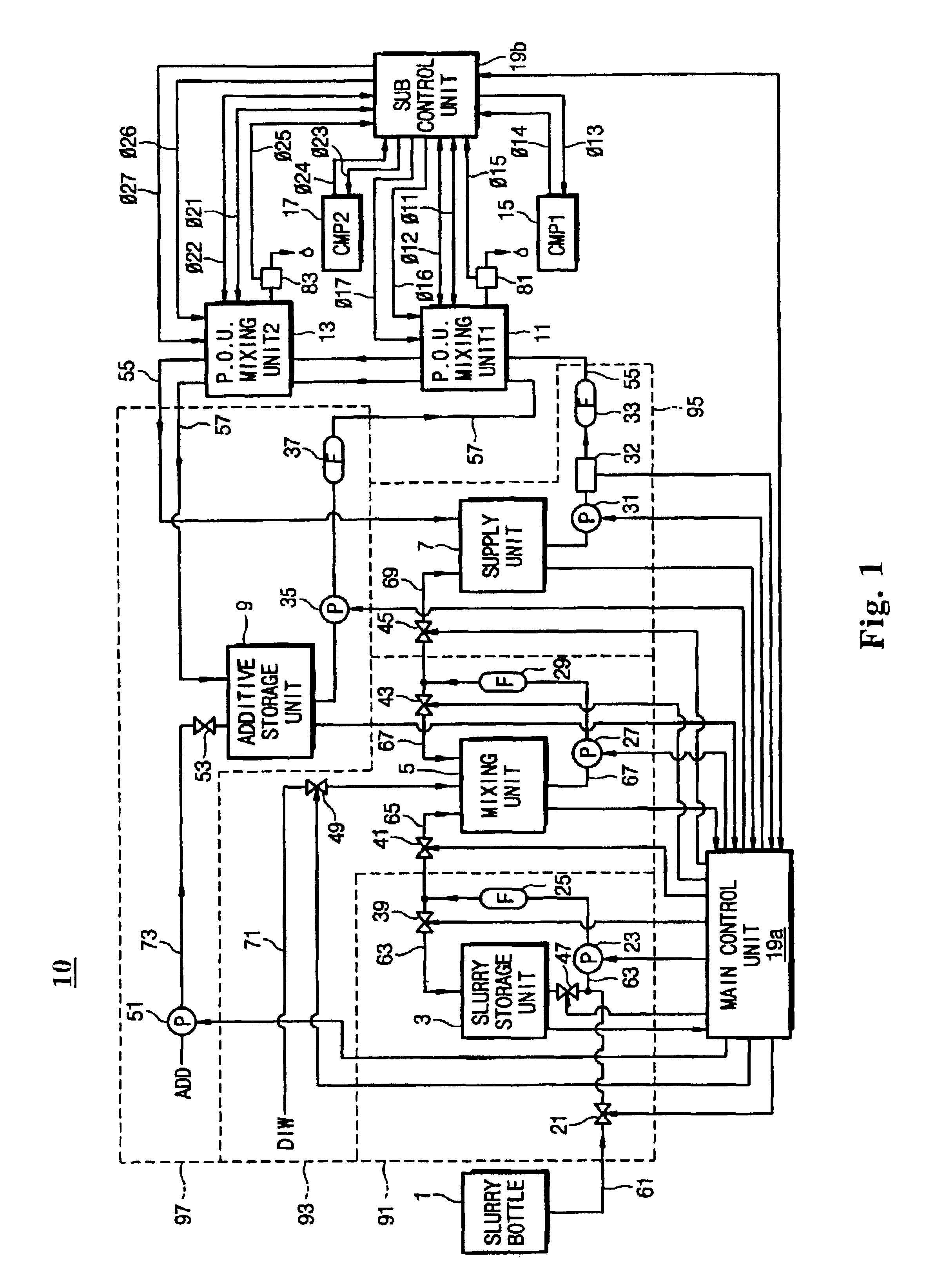
[0030]FIG. 1 illustrates a schematic diagram of a slurry supply apparatus 10 according to a preferred embodiment of the present invention.

[0031]Referring to FIG. 1, a slurry bottle 1 is connected via a first slurry conduit 61 to a slurry circulation loop line 63, which is installed outside a slurry storage unit 3. Preferably, first slurry conduit 61 is connected to slurry circulation loop line 63 at a point between a first pump 23 and an outlet of slurry storage unit 3. An inlet of slurry circulation loop line 63 is connected to the outlet of slurry storage unit 3, and an outlet of slurry circulation loop line 63 is extended into an entry port of slurry storage unit 3. Also, a first pump 23 is installed at a predetermined region in slurry circulation loop li...


PUM

PropertyMeasurementUnit
Flow rateaaaaaaaaaa

Abstract

A computer-controlled slurry supplying apparatus for providing abrasive slurry to a chemical mechanical polishing (CMP) machine in a semiconductor manufacturing process preferably comprises a storage portion for accepting and storing a quantity of undiluted slurry, a mixing portion for accepting undiluted slurry from the storage portion and mixing with a diluting solution to created a diluted slurry, a supply portion for holding the diluted slurry, and at least one point-of-use mixing unit for mixing at least one chemical additive to the diluted slurry at or near a dispensing nozzle at the point of application. Each of the above portions of the slurry supplying apparatus further includes a re-circulation means for keep solutions in a mixed and agitated state. A method for using the slurry supplying apparatus comprises steps of controllably operating various valves, pumps, and sensors to maintain a desired slurry composition and flow rate.

Description

BACKGROUND OF THE INVENTION[0001]1. Field of the Invention[0002]The present invention relates to generally to supplying slurry in manufacturing processes and, more particularly, to a method of supplying slurry and a slurry supply apparatus for supplying slurry to a chemical mechanical polishing (CMP) machine used in planarizing surfaces of semiconductor devices during semiconductor fabrication.[0003]2. Description of Related Art[0004]As semiconductor devices become more highly integrated, a planarization technique using a chemical mechanical polishing (CMP) machine is typically employed. The CMP machine typically uses a slurry comprised of an abrasive material and a diluting agent and possibly a curing agent to create a solution that has a polishing selectivity with respect to an underlying layer that acts as a CMP stopping layer. Selection of a particular slurry depends on the semiconductor layers to be palanarized. For example, a silica-based (SiO2) slurry is typically used for pl...

Claims


Application Information

Patent Timeline
IPC IPC(8): B01F3/12B24B57/02B24B57/00B01F15/00B24B37/00H01L21/304
CPCB01F3/1221B01F3/1271B24B57/02B01F2003/1285B01F15/00123B01F23/581B01F23/53B01F23/59B01F35/20H01L21/304B01F35/21
Inventor KIM, SUE-RYEONKIM, SEUNG-UNCHAE, SEUNG-KILEE, JE-GUAHN, SEUNG-HOON
Owner SAMSUNG ELECTRONICS CO LTD
Why Eureka
Try Eureka