
Method and apparatus for simultaneous heat and mass transfer utilizing a carrier-gas

a carrier gas and simultaneous heat and mass transfer technology, applied in lighting and heating apparatus, combustion-air/fuel-air treatment, separation processes, etc., can solve the problems of increasing the maintenance and/or pretreatment costs of ro operations, requiring costly phase changes of liquids, and reducing the efficiency of ro in purifying water containing non-filterable suspended particles, etc., to achieve the effect of increasing the concentration of water vapor

Inactive Publication Date: 2005-06-28
THE ARIZONA BOARD OF REGENTS ON BEHALF OF THE UNIV OF ARIZONA +1
View PDF16 Cites 52 Cited by
  • Summary
  • Abstract
  • Description
  • Claims
  • Application Information

AI Technical Summary

Benefits of technology

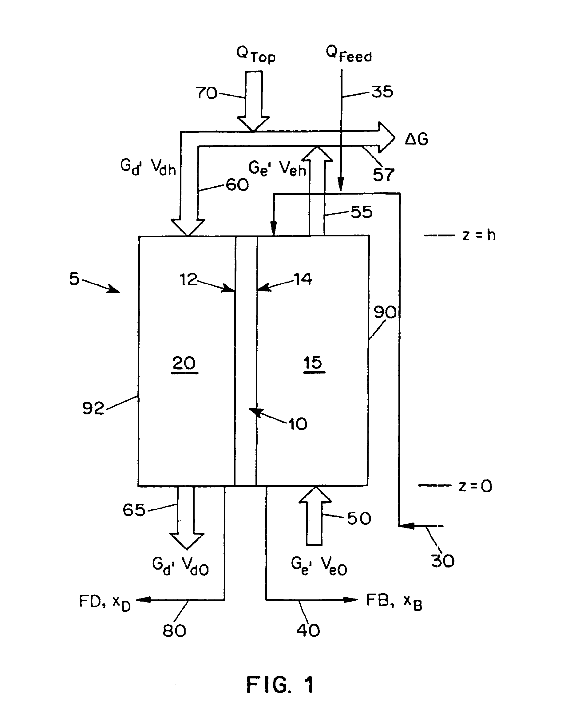
[0011]In another embodiment of the present invention, the apparatus further includes a wetting material placed on top of the evaporation side of the heat transfer wall. In various other embodiments, the heating apparatus can be any of the following: (i) a boiler, which provides steam to the carrier gas; (ii) a heat exchanger, wherein steam from a boiler is brought into thermal communication with the carrier gas; (iii) a desiccant / heat exchanger, wherein a slip stream is taken from the carrier gas and reacted with a desiccant and the heat produced by the reaction is thermally communicated to the remainder of the carrier gas; and (iv) a liquid / contactor, wherein a reactant reacts with the carrier gas, thereby increasing the concentration of the water vapor in the remaining carrier gas.

Problems solved by technology

This preference results from the fact that other technologies utilize techniques which require costly phase changes of the liquid, such as boiling a liquid into a gas.
However, RO is ineffective in purifying water containing non-filterable suspended particulates.
Many rivers, such as the Colorado River, contain silt in the 1 micron range which can foul RO membranes, thereby increasing the maintenance and / or pretreatment costs of RO operations.
Furthermore, feed waters require expensive pre-treatments in order to protect and extend the life of the membranes.
Unfortunately, electrically driven MVC plants consume more electricity than RO units for sea water desalination.
As the GOR increases so does the equipment capital cost.
However, a staged configuration was required to limit the mixing by the pumps of the liquid compositions and temperatures at different locations of the apparatus.
Accordingly, the increased complexity of these apparatus was detrimental to economic and reliable operation.

Method used


Image

  • Method and apparatus for simultaneous heat and mass transfer utilizing a carrier-gas
  • Method and apparatus for simultaneous heat and mass transfer utilizing a carrier-gas
  • Method and apparatus for simultaneous heat and mass transfer utilizing a carrier-gas

Examples


example 1

[0063]The Dewvaporation apparatus of the present invention avoids the use of multiple pumps effectively by letting gravity produce the liquid movement. A laboratory bench scale tower containing an effective total heat transfer area of 20 ft2 (1.8 m2) was built. The height of the tower was 8 feet (2.44 m) and 6 inches (15.24 cm) wide. The heat transfer wall was made of plastic sheets (75 microns thick) with ¼ inch spacing between the heat transfer wall and the outer wall of the apparatus. The shell of the apparatus was made of twin wall polycarbonate plastic sheets (commercially available as Lexanthermoclear sheet twin wall ¼ inch sheets from the Structural Products Division of General Electric Company) to give support for the apparatus. The outside of the apparatus was further covered with polystyrene foam to provide insulation. Initial data were conducted using brackish water having 850 ppm TDS, as shown in Table 2.

[0064]

TABLE 2Energy Reuse Factor and Production Density DataTempera...

example 2

Scaling Experiments

[0066]The scaling experiments were carried out on a bench scale unit, which consisted of a thermal control grill mounted vertically with a sample of a plastic heat transfer sheet attached to its surface.

[0067]The unit was covered with a plastic wall allowing the air to rise in temperature in order to simulate the operation of the tower. Salt solution was prepared according to ASTM method number D1141-90 (1992) with a salinity of 35 g / Kg. Moreover, temperatures of the liquid film were measured along the center of the wall using thermocouples.

[0068]Results showed that after 82% to 85% recovery of water, solids were observed. However, the solids were washed down the plastic wall without adhering to it. The Dewvaporation process concentrates salt solution from 3.5 wt % to 10 wt % which is 67% water recovery, so potential scaling does not appear to be a dominant factor in this process.

example 3

1000 gal / day (4 m3 / day) Desalination Facility

[0069]The basis for a cost estimation is a 1000 gal / day brackish water unit (FIG. 7) with a factor f=15. The capital charge factor 0.12 was based on the current prime interest rate of 8.5% and an equipment life of 15 years (Table 3). The feed may contain up to 8000 ppm TDS resulting in a condensate of less than 1 ppm TDS.

[0070]

TABLE 3Cost Summary of 1000 gal / day unitPlastic heat transfer wall (4400 ft2*$0.096 / ft2)$425Cover$1004 pumps (feed liquid and hot water recycle)$2501 air fan$441 hot water, 80% efficiency$485Pipes and fittings$100Assembly (2 workers at $10 / hr for 8 hrs)$160Total manufacturing cost$1,564Manufactures gross margin$500Total Unit Cost 2064**$2.06 / gallon day or $0.52 / cubic meter day

[0071]The major elements of the equipment costs are the plastic heat transfer wall and the hot water heater. Each of which accounts for about 30% of the manufacturing cost. A reduction in the size of the heat transfer wall can be achieved by h...


PUM

PropertyMeasurementUnit
pressureaaaaaaaaaa
sizeaaaaaaaaaa
pressuresaaaaaaaaaa

Abstract

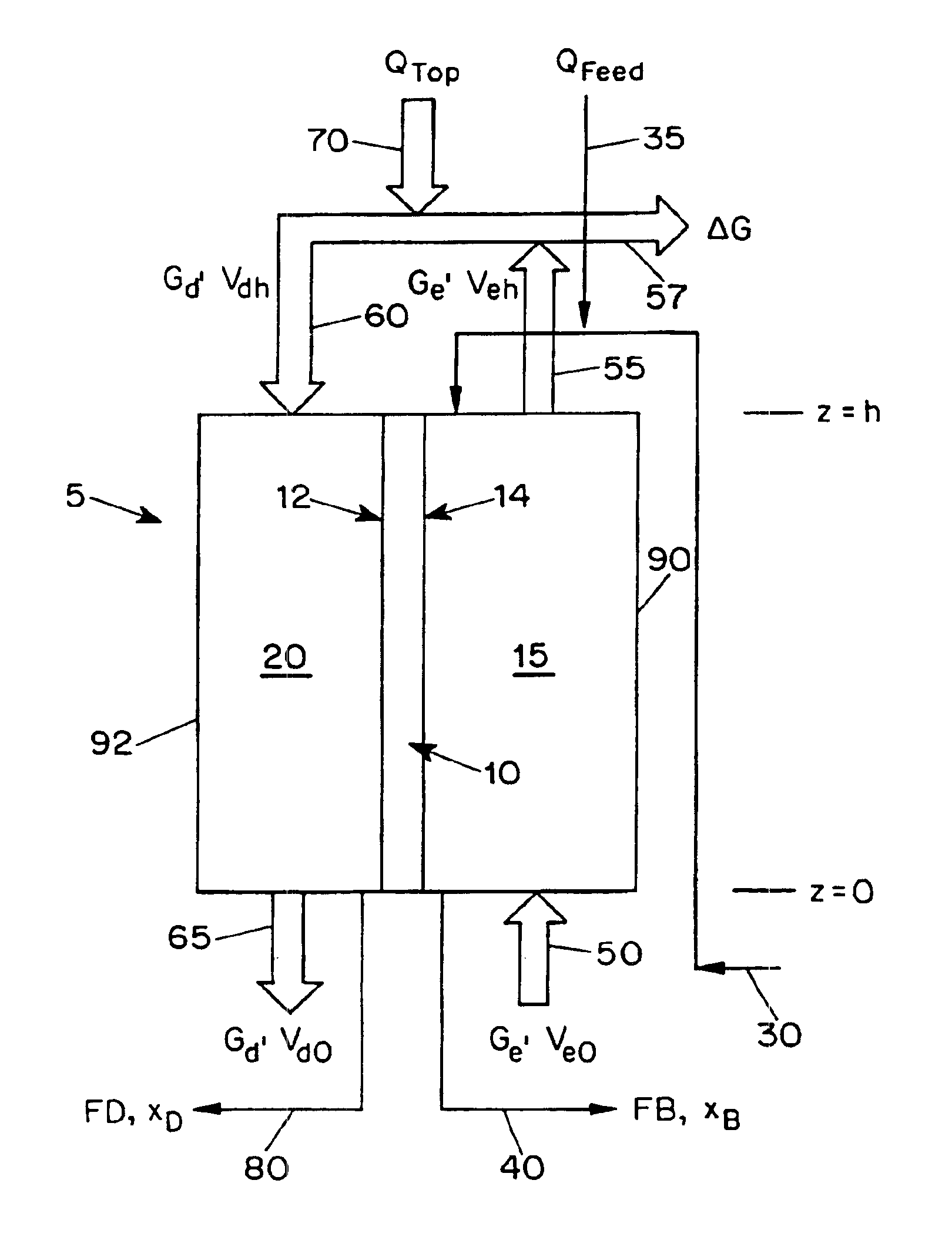
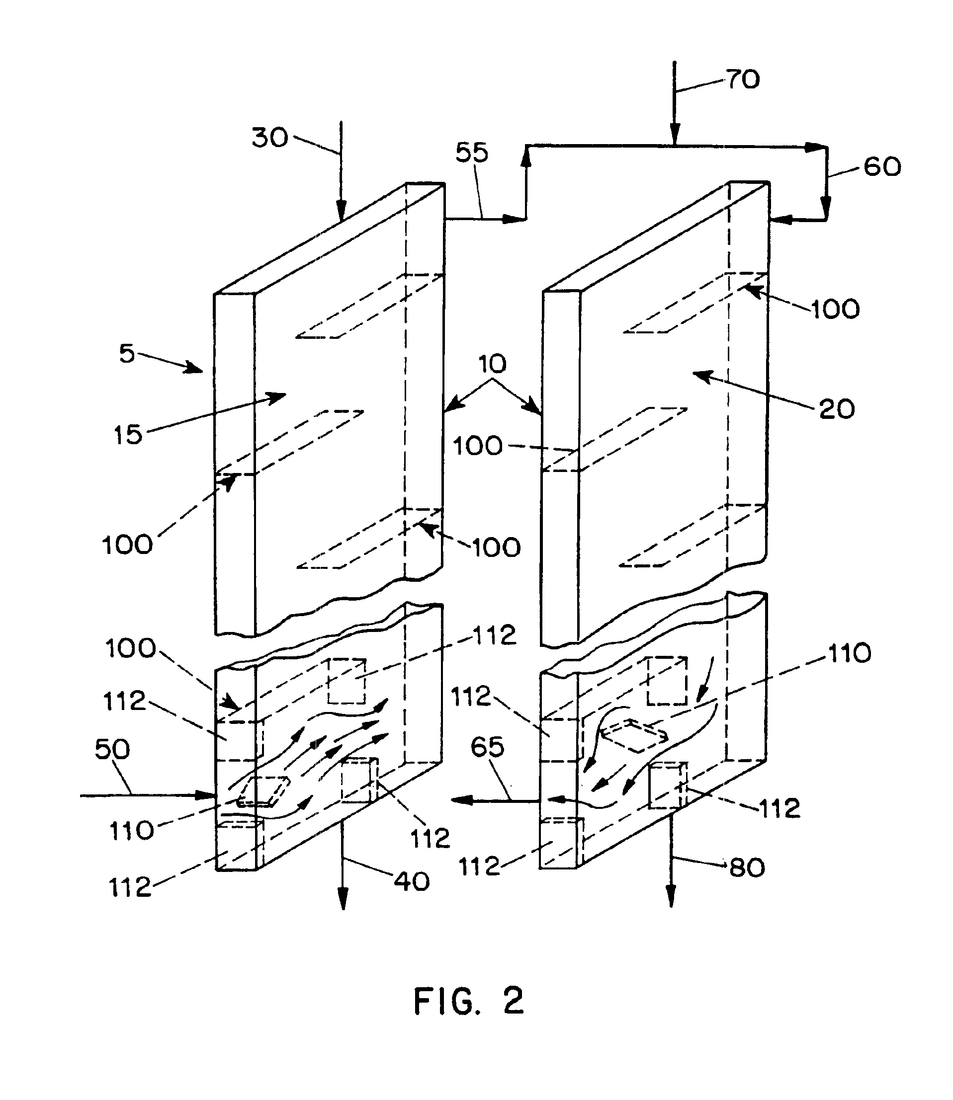
The present application is directed to a continuous contacting apparatus for separating a liquid component from a liquid mixture. The apparatus comprises: (i) an evaporation chamber (15) having first and second ends, an inlet (50) and an outlet (55) for a carrier gas, and an inlet (30) and an outlet (40) for a liquid mixture, wherein the inlet (30) for the liquid mixture and the outlet (55) of the carrier gas are located on the first end of the evaporation chamber (15); (ii) a dew-formation chamber (20) having an inlet (60) and an outlet (65) for a carrier gas and an outlet for the separable liquid component (80), wherein the inlet for the carrier gas (60) of the dew-formation chamber (20) is situated in a countercurrent manner to the inlet for the carrier gas of the evaporation chamber; (iii) a common heat transfer wall (10) providing thermal communication between the evaporation chamber (15) and the dew-formation chamber (20); (iv) a feeding device for providing the liquid mixture onto the evaporation side of the heat transfer wall; (v) an air mover for controlling a flow of a carrier gas through the chambers, wherein the gas flow in the evaporation chamber is countercurrent to the gas flow in the dew-formation chamber; and (vi) a heating apparatus for heating the carrier gas from the outlet of the evaporation chamber, wherein the heated carrier gas is directed to flow into the inlet of the dew-formation chamber. Also described is a process for separating a liquid component from a liquid mixture in a continuous contacting manner comprising employing such an apparatus for such separation.

Description

CROSS REFERENCE TO RELATED APPLICATION[0001]This application is a 371 of PCT / US00 / 20396, filed Jul. 26, 2000, which claims priority of U.S. provisional application Ser. No. 60 / 145,692 filed Jul. 26, 1999, which is incorporated by reference herein.FEDERALLY SPONSORED RESEARCH[0002]This project was partially funded by financial assistance provided by the United States Government through the Bureau of Reclamation, Financial Agreement Nos. 98-FC-81-0049 and 99-FC-81-0186; and the United States Government may own certain rights to this invention.FIELD OF THE INVENTION[0003]This invention relates to a method and apparatus for the efficient separation of: (i) liquid mixtures containing dissolved solids; or (ii) liquid mixtures, or both, wherein one or more liquid components have differing vapor pressures from the remaining components. In particular, the present invention relates to a method and apparatus for utilizing a carrier gas to separate a liquid component from a liquid mixture.BACKG...

Claims


Application Information

Patent Timeline
Patent Type & Authority Patents(United States)
IPC IPC(8): B01D1/22B01D3/34B01D3/42
CPCB01D1/22B01D3/346B01D3/42Y10S165/914Y10S165/162Y02W10/37
Inventor BECKMAN, JAMES R.
Owner THE ARIZONA BOARD OF REGENTS ON BEHALF OF THE UNIV OF ARIZONA
Learn More