
Patch and cavity for producing dual polarization states with controlled RF beamwidths

a dual polarized antenna and beamwidth control technology, applied in the field of electromagnetic signals communication antennas, can solve the problems of reducing the efficiency of heat transfer function, reducing the efficiency of heat transfer, and reducing the amount of passive intermodulation (pim)

Inactive Publication Date: 2005-06-28
ANDREW CORP
View PDF24 Cites 40 Cited by
  • Summary
  • Abstract
  • Description
  • Claims
  • Application Information

AI Technical Summary

Benefits of technology

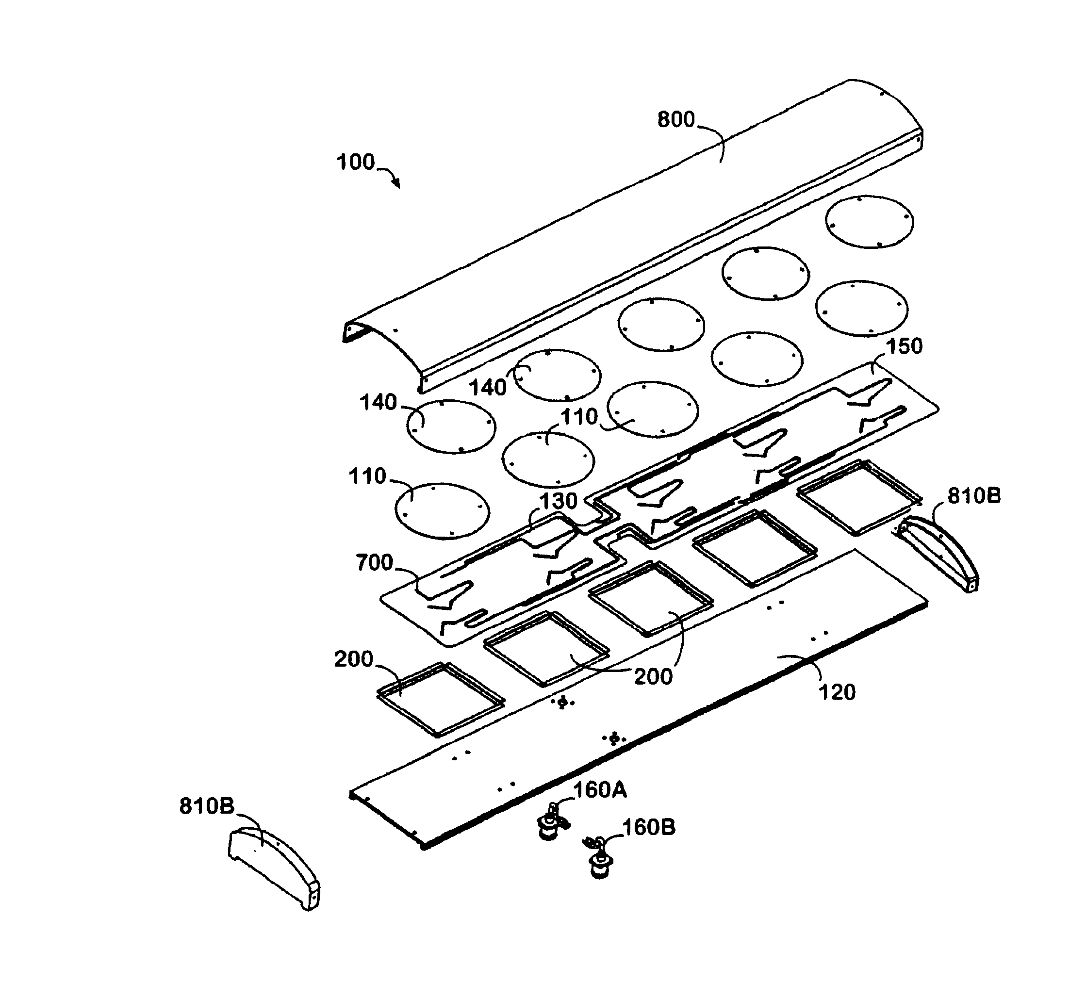
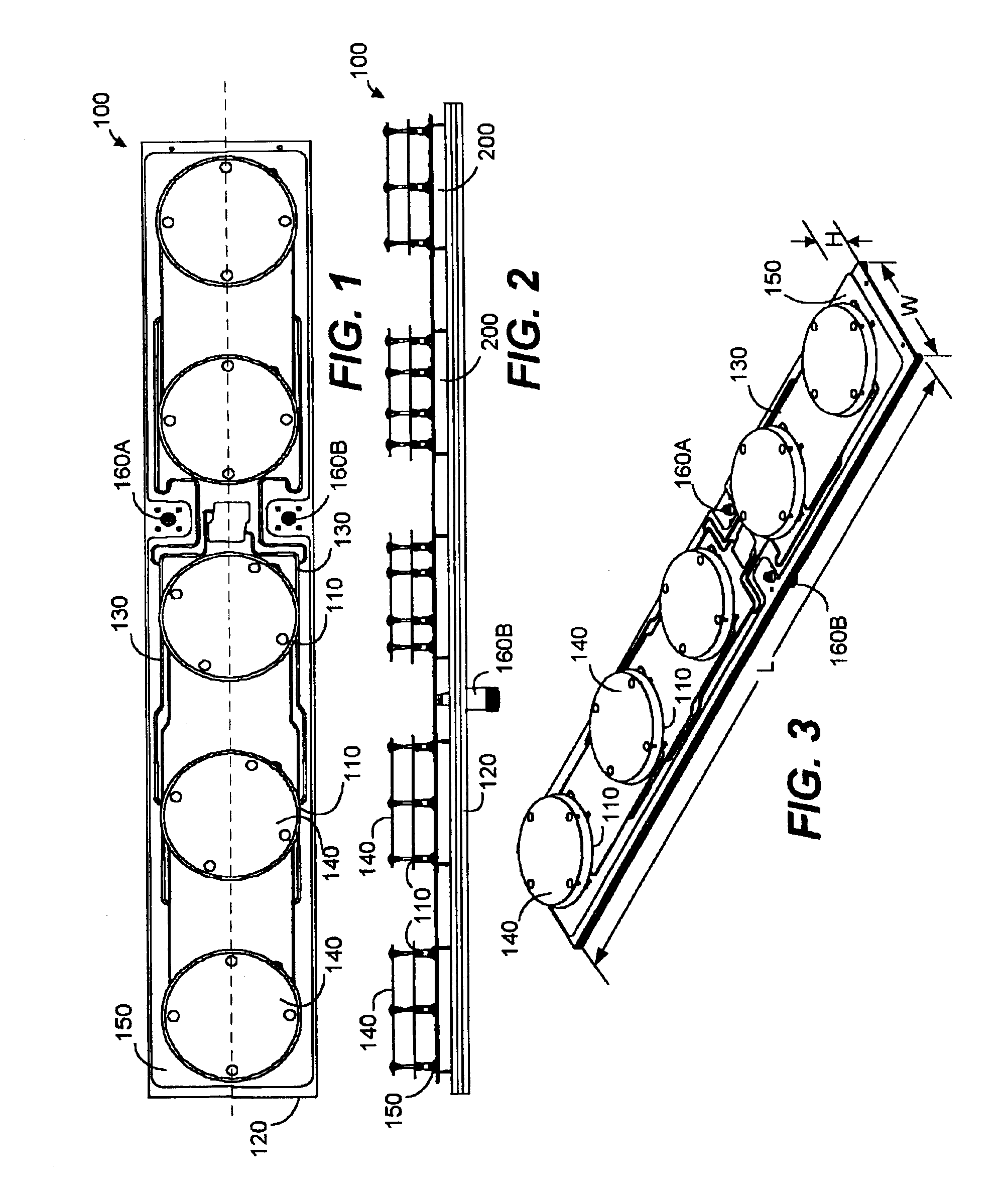
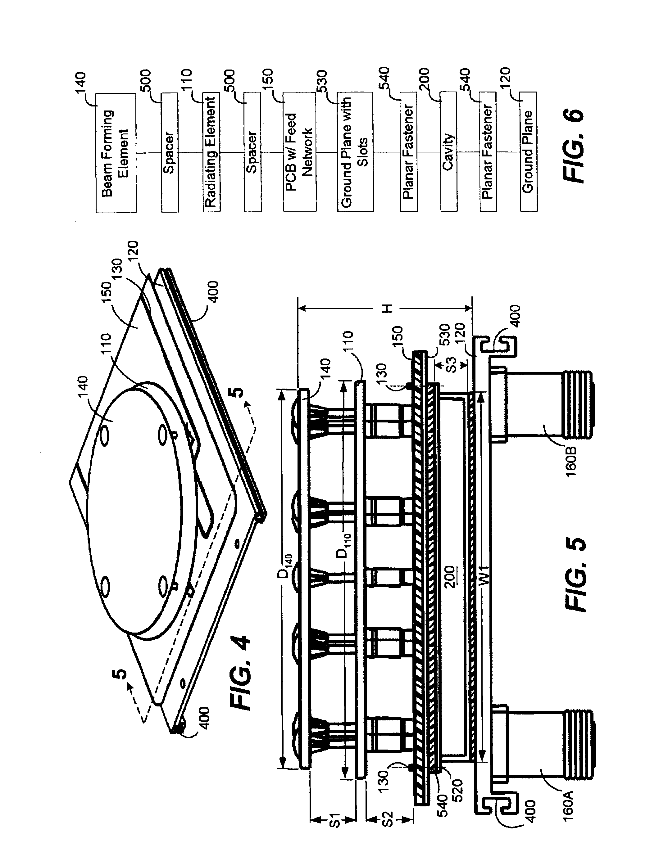
[0011]This enhanced functionality can be achieved with a compact antenna system, where the antenna system (without a radome) can typically have a height of approximately less than one seventh ({fraction (1 / 7)}) of a wavelength and a width that is less than or equal to six-tenths (0.6) of a wavelength. With a radome, the antenna system can have a height of approximately one-fifth (⅕) of a wavelength. The antenna system can comprise one or more patch radiators and a non-resonant patch separated from each other by an air dielectric and by relatively small spacer elements. The patch radiators and non-resonant patch can have predefined shapes for increasing polarization discrimination.
[0020]While providing a product that can be manufactured efficiently, the present invention also provides an efficient RF antenna system. The RF energy produced by the cavity, slots, and stubs can then be coupled to one or more lower patch radiators. The one or more lower patch radiators can then resonate and propagate RF energy with a wide range of H-plane beamwidths that can extend between approximately sixty-five (65) and ninety (90) degrees.

Problems solved by technology

However, dual polarization or polarization diversity typically requires a significant amount of hardware that can be rather complex to manufacture.
Further, conventional dual polarized antennas typically cannot provide symmetrical radiation patterns where respective electric field (E) and magnetic field (H) plane beamwidths are substantially equal.
Additionally, conventional antenna systems usually cannot provide for a wide range of magnetic field (H) plane beamwidths from a compact antenna system.
In other words, the conventional art typically requires costly and bulky hardware in order to provide for a wide range of operational beamwidths, where beamwidth is measured from the half-power points (−3 dB to −3 dB) of a respective RF beam.
Such manufacturing techniques can make an antenna system more susceptible to PIM and therefore, performance of a conventional antenna system can be substantially reduced.
A further problem in the conventional art is the ability to effectively control the beamwidth of the resulting radiation patterns of a dual polarized antenna system.
The conventional art typically does not provide for any simple techniques for controlling beamwidth of a dual polarized antenna system.
Unrelated to the problems discussed above, antenna designers are often forced to design antennas in a backward fashion.
Requiring antenna designers to build an antenna to fit within a radome as opposed to designing or sizing a radome after an antenna is constructed creates many problems for antenna designers.
Such a requirement is counterproductive to antenna design since antenna designers recognize that the size of antennas are typically a function of their operating frequency.

Method used


Image

  • Patch and cavity for producing dual polarization states with controlled RF beamwidths
  • Patch and cavity for producing dual polarization states with controlled RF beamwidths
  • Patch and cavity for producing dual polarization states with controlled RF beamwidths

Examples


Embodiment Construction

[0041]The antenna of the present invention can solve the aforementioned problems and is useful for wireless communications applications, such as personal communication services (PCS) and cellular mobile radio telephone (CMR) service. The antenna of the present invention can use polarization diversity to mitigate the deleterious effects of fading and cancellation resulting from a complex propagation environment. The antenna system can include a patch radiator, a printed circuit board disposed adjacent to the patch radiator, and plurality of slots disposed within a ground plane of the printed circuit board. The antenna further includes a cavity disposed adjacent to the ground plane of the printed circuit board and a second ground plane disposed adjacent to the cavity. The antenna system radiates RF energy having dual simultaneous polarization states and having substantially rotationally symmetric radiation patterns.

[0042]Turning now to the drawings, in which like reference numerals re...


PUM


Abstract

An antenna system can generate RF radiation fields having dual simultaneous polarization states and having substantially rotationally symmetric radiation patterns. The antenna system generates RF radiation patterns where the beamwidths of respective RF fields for respective radiating elements are substantially equal and are relatively large despite the compact, physical size of the antenna system. The antenna system can include one or more patch radiators and a non-resonant patch separated from each other by an air dielectric and by relatively small spacer elements. The patch radiators and non-resonant patch can have predefined shapes for increasing polarization discrimination. The lower patch radiators can be mounted to a printed circuit board that can include an RF feed network and a ground plane which defines a plurality of symmetrically, shaped slots. The slots within the ground plane of the printed circuit board can be excited by stubs that are part of the feed network of the printed circuit board. The slots, in turn, can establish a transverse magnetic mode of RF radiation in a cavity which is disposed adjacent to the ground plane of the printed circuit board and a ground plane of the antenna system. The feed network of the printed circuit board can be aligned with portions of the cavity such that the portions of the cavity function as a heat sink for absorbing or receiving thermal energy produced by the feed network.

Description

[0001]This application is a continuation of U.S. application Ser. No. 09 / 785,033, filed Feb. 16, 2001, entitled, “Method and System for Producing Dual Polarization states with Controlled RF Beamwidths”, the entire contents of which are hereby incorporated by reference.TECHNICAL FIELD[0002]The present invention is generally directed to an antenna for communicating electromagnetic signals, and relates more particularly to a planar array antenna having patch radiators exhibiting dual polarization states and producing substantially rotationally symmetric radiation patterns with controlled beamwidths.BACKGROUND OF THE INVENTION[0003]Diversity techniques at the receiving end of a wireless communication link can improve signal reception without additional interference. One such diversity technique is generating dual simultaneous polarization states. The term “dual simultaneous polarization states” typically means that an antenna has at least two different radiators, where each radiator sim...

Claims


Application Information

Patent Timeline
Patent Type & Authority Patents(United States)
IPC IPC(8): H01Q21/24H01Q21/06H01Q25/00
CPCH01Q21/065H01Q25/002H01Q21/24
Inventor CARSON, JAMES C.PHILLIPS, SARA
Owner ANDREW CORP
Learn More