Optical interference color display and optical interference modulator

a color display and color display technology, applied in optics, instruments, optical filters, etc., can solve the problems of different degrees of optical interference, poor optical utilization of light sources, and energy wastage of back light modules, etc., and achieve the effect of reducing the cost of optical interference modulators

Inactive Publication Date: 2005-06-28
SNAPTRACK
View PDF2 Cites 299 Cited by
  • Summary
  • Abstract
  • Description
  • Claims
  • Application Information

AI Technical Summary

Benefits of technology

[0015]Accordingly, one object of the present invention is to provide an optical interference color display and optical interference modulator each having an

Problems solved by technology

However, most LCD still has a number of drawbacks including narrow visual angle, moderate response time, need for a color filter for full coloration, and need for a polarizer leading to a poor optical utilization of light source and energy wastage by a back light module.
Because light passing through air gap of different thickness may result in different degree of optical interference, different colors are produced.
In addition, each optical interference modulator consumes very little electric power, quick to

Method used


Image

  • Optical interference color display and optical interference modulator
  • Optical interference color display and optical interference modulator
  • Optical interference color display and optical interference modulator

Examples


Embodiment Construction

[0025]Reference will now be made in detail to the present preferred embodiments of the invention, examples of which are illustrated in the accompanying drawings. Wherever possible, the same reference numbers are used in the drawings and the description to refer to the same or like parts.

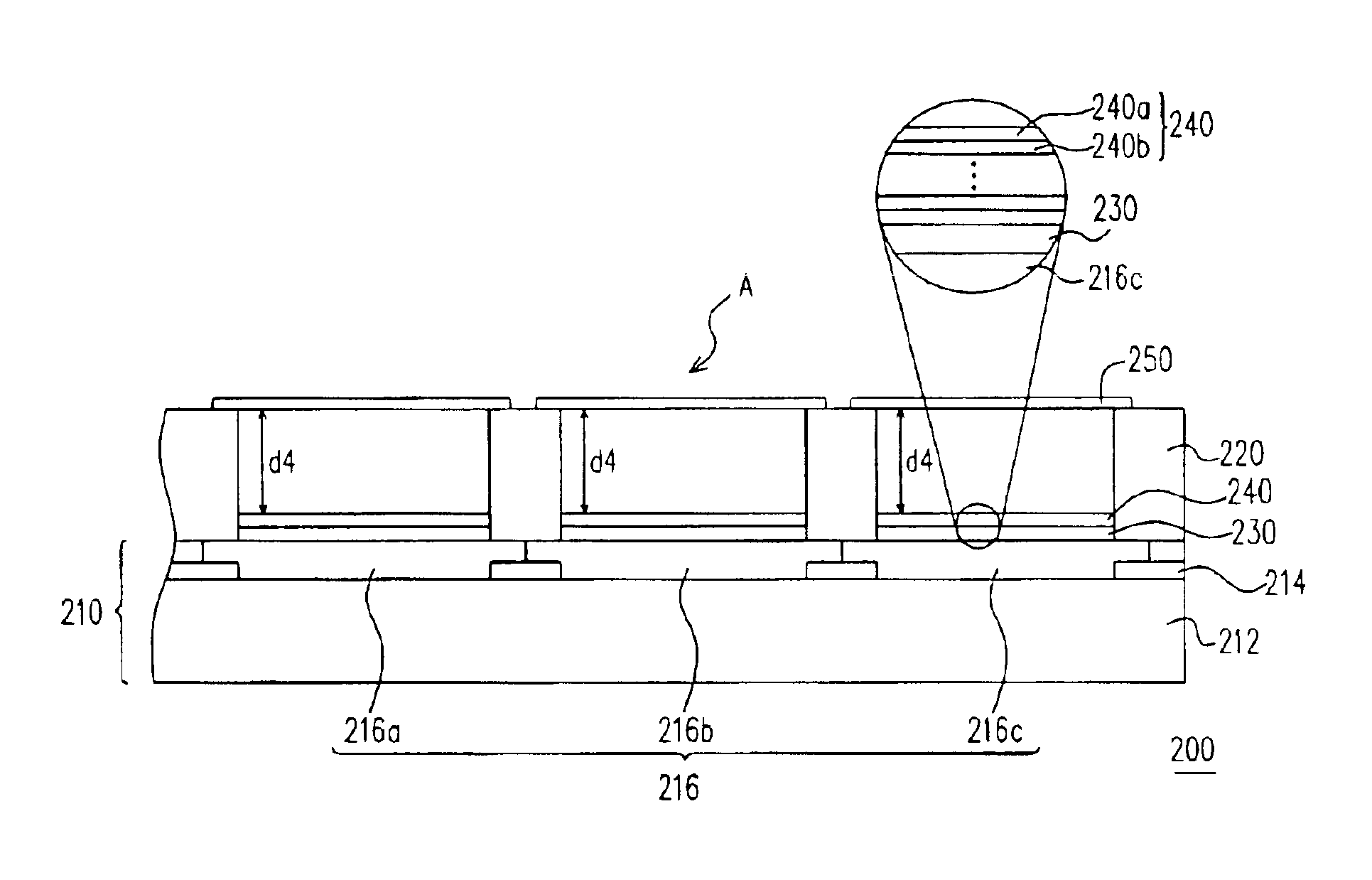
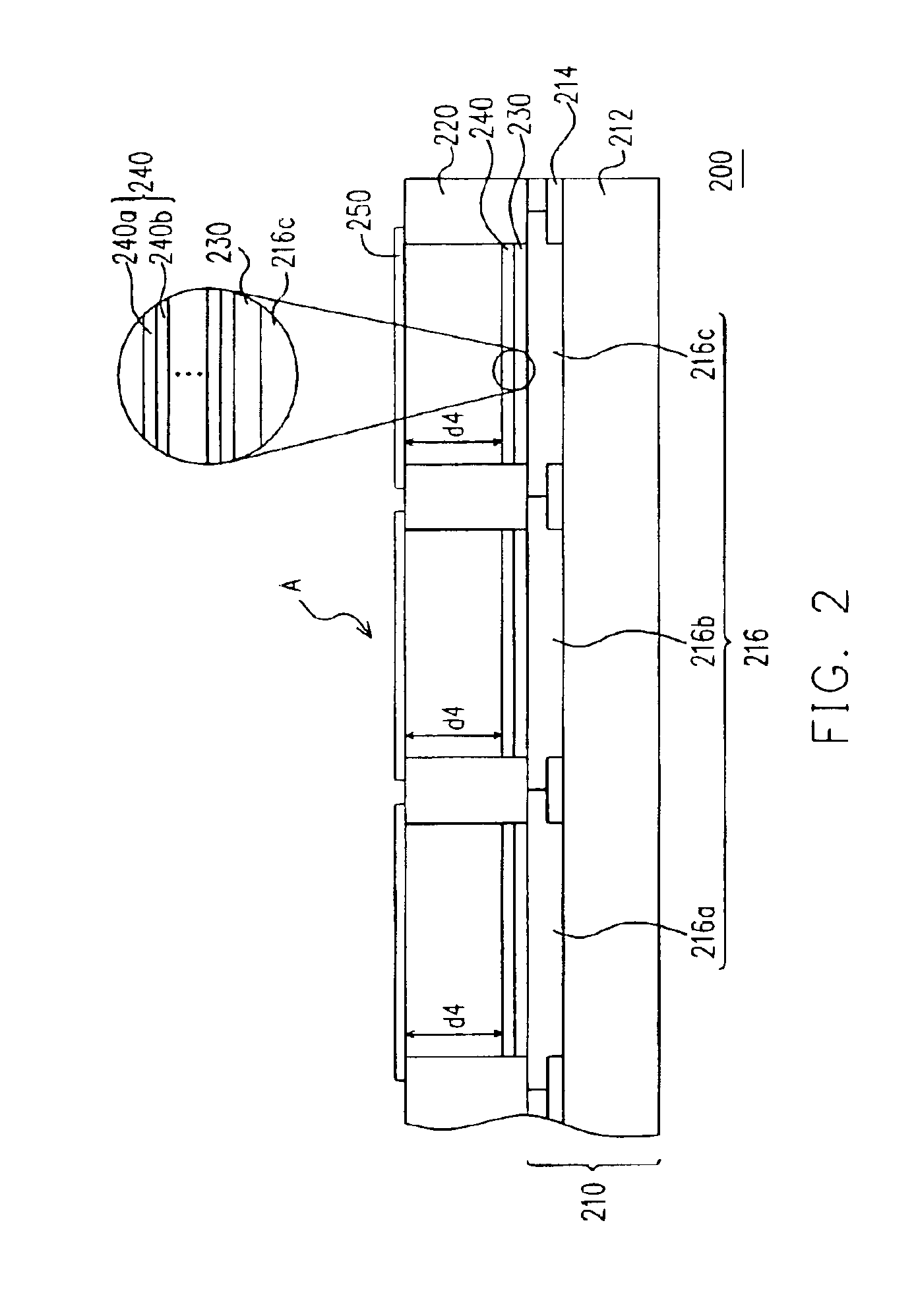
[0026]FIG. 2 is a schematic sectional view of an optical interference color display according to one preferred embodiment of this invention. As shown in FIG. 2, the optical interference color display 200 mainly comprises a color filtering substrate 210, a patterned support layer 220, a plurality of first electrodes 230, a plurality of optical films 240 and a plurality of second electrodes 250.

[0027]The color filtering substrate 210 includes a substrate 212, a black matrix 214 and a plurality of color filtering films 216. The substrate is a transparent substrate fabricated using a material including, for example, glass, polymer plastic or other transparent material. The black matrix 214 having a plura...


PUM


Abstract

An optical interference color display is provided. The optical interference color display comprises a color filtering substrate, a patterned support layer, a plurality of first electrodes, a plurality of optical films and a plurality of second electrodes. The patterned support layer and the first electrodes are positioned on the color filtering substrate with the patterned support layer between the first electrodes. The optical films are positioned on the first electrodes. The second electrodes is positioned over the first electrodes and supported through the patterned support layer such that an air gap with identical thickness is produce between every pair of second electrode and first electrode. Using the color filtering substrate to show color images, air gap between the first electrodes and the second electrodes are identical and hence simplifies the manufacturing process.

Description

CROSS REFERENCE TO RELATED APPLICATIONS[0001]This application claims the priority benefit of Taiwan application serial no. 91137638, filed on Dec. 27, 2002.BACKGROUND OF THE INVENTION[0002]1. Field of Invention[0003]The present invention relates to an interference color display and an optical interference modulator. More particularly, the present invention relates to an interference color display and an optical interference modulator with a single air gap and color filtering film design.[0004]2. Description of Related Art[0005]At present, lightweight and slim flat panel displays such as liquid crystal display (LCD), organic light-emitting device (OLED) or plasma display panel (PDP) are widely adopted in our everyday life. In particular, liquid crystal panels have become one of the mainstream displays. However, most LCD still has a number of drawbacks including narrow visual angle, moderate response time, need for a color filter for full coloration, and need for a polarizer leading t...

Claims


Application Information

Patent Timeline
IPC IPC(8): G02B26/00G02B5/20G02B26/02G02F1/13G02F1/1335
CPCG02B26/001G02B5/201G02F1/13
Inventor LIN, WEN-JIANTSAI, HSIUNG-KUANG
Owner SNAPTRACK
Why Eureka
Try Eureka