Concentric co-planar multiband electro-acoustic converter

Inactive Publication Date: 2005-06-28
SAGREN ANDERS
View PDF2 Cites 7 Cited by
  • Summary
  • Abstract
  • Description
  • Claims
  • Application Information

AI Technical Summary

Benefits of technology

[0014]Thanks to the inventive design of the magnetic structures makes it possible to achieve efficient drive units with a small diameter and thus overcoming the problems associated with prior art compound drive units.
[0015]Thanks to the system of the present invention it is possible to design amplifying systems capable of amplifying sound in reverberant environments without the drawbacks associated with prior art systems.
[0016]One advantage afforded by the present invention is that it provides electro acoustic converter providing a coherent wave-front for the emitted sound waves in a full frequency range. The coherence of the emitted sound waves does allow, for example, the use of (multi

Problems solved by technology

This time difference between sounds received results in a phase difference between the sounds received at the listening position.
This will limit, but not completely eliminate, the problems caused by the phase difference.
More problematic is to amplify sound in acoustically complex, non-mute, often older premises such as churches, theaters and concert halls.
When the sound, after a multitude of reflections, reaches the listener it will be highly distorted.
To damp the hall to obtain a near acoustic mute environment is in most cases not an attractive solution, since the acoustic character of for example a church is perceived as an essential part of the sound experience of such a premises.
However the low frequency diaphragm is positioned at the front of the loudspeaker unit whereas the high frequency diaphragm is positioned at the rear of the loudspeaker unit and this

Method used


Image

  • Concentric co-planar multiband electro-acoustic converter
  • Concentric co-planar multiband electro-acoustic converter
  • Concentric co-planar multiband electro-acoustic converter

Examples


Embodiment Construction

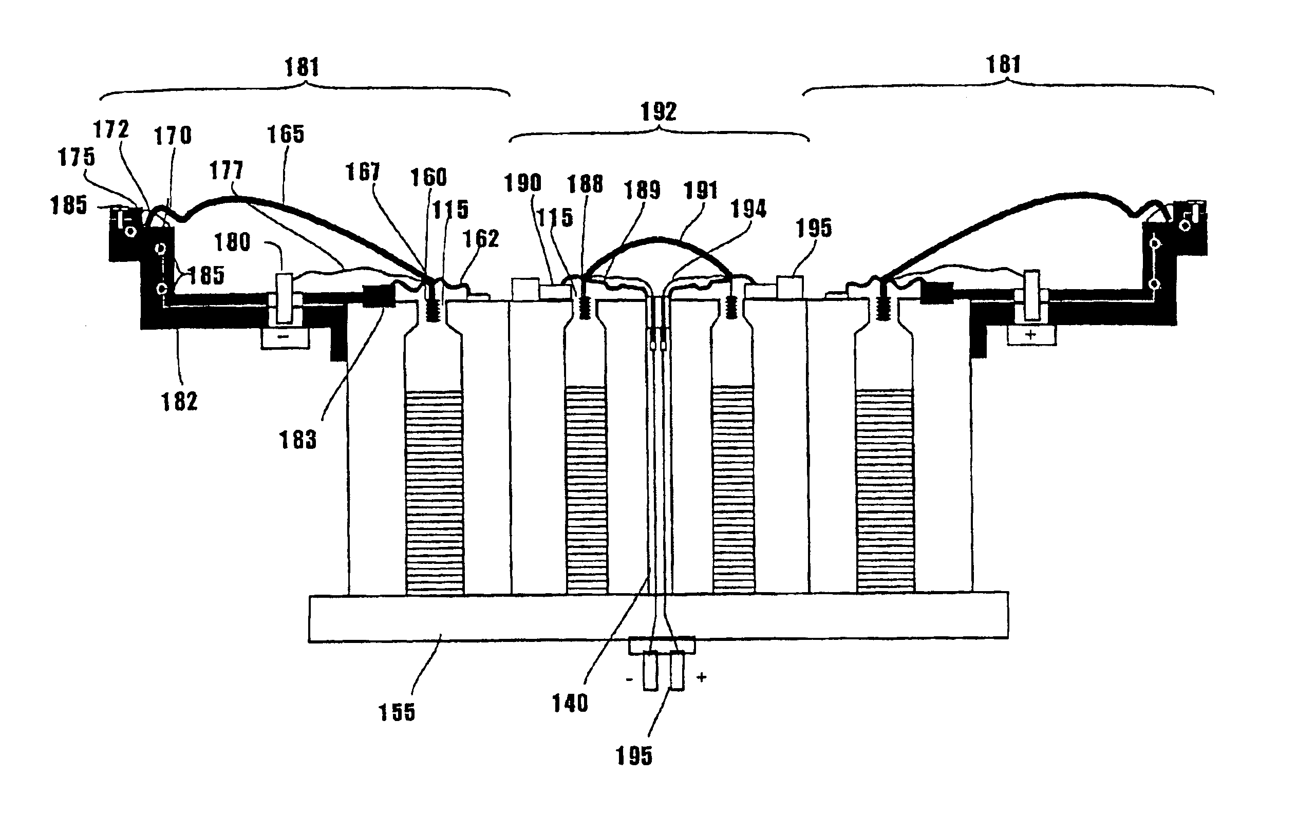
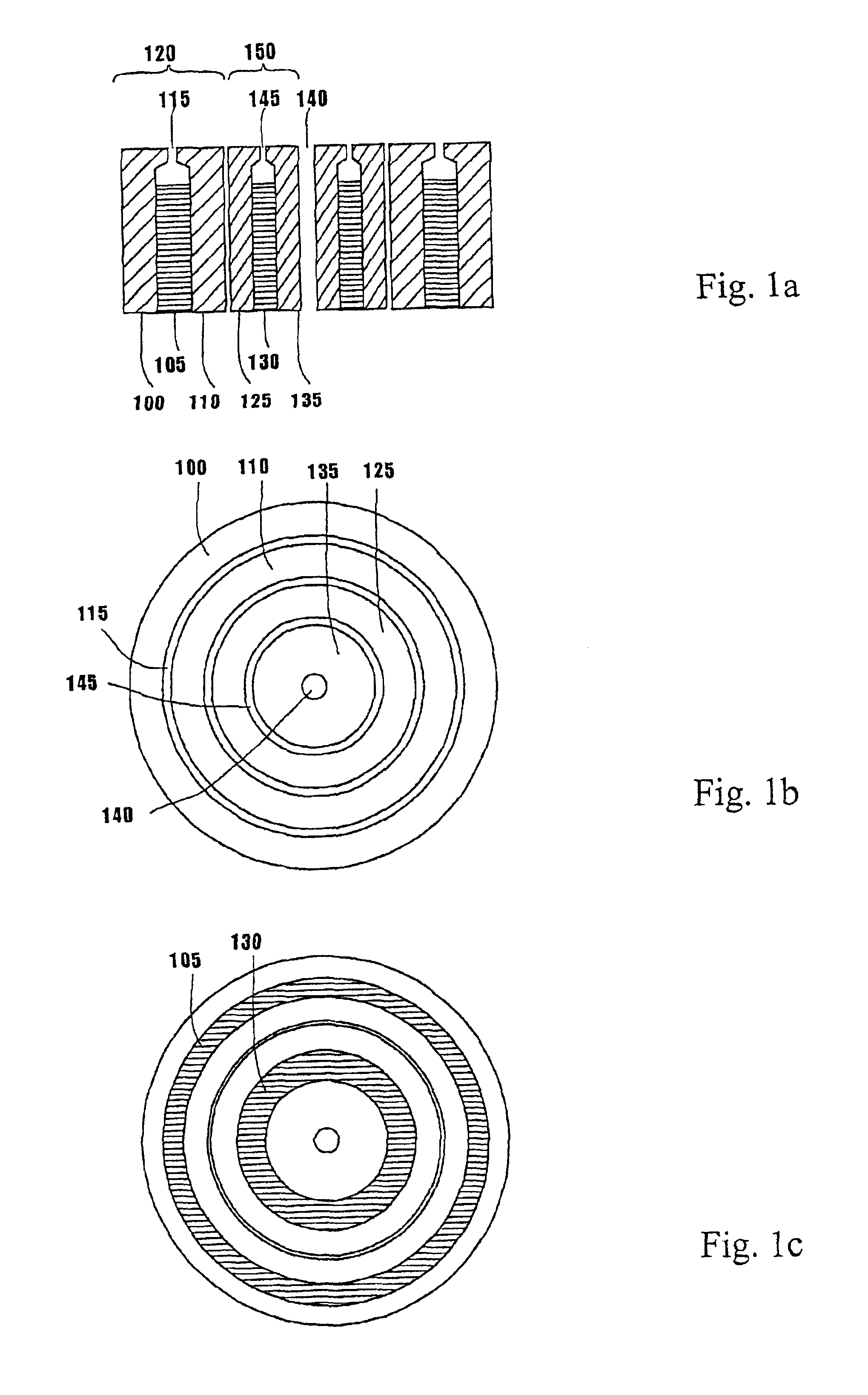
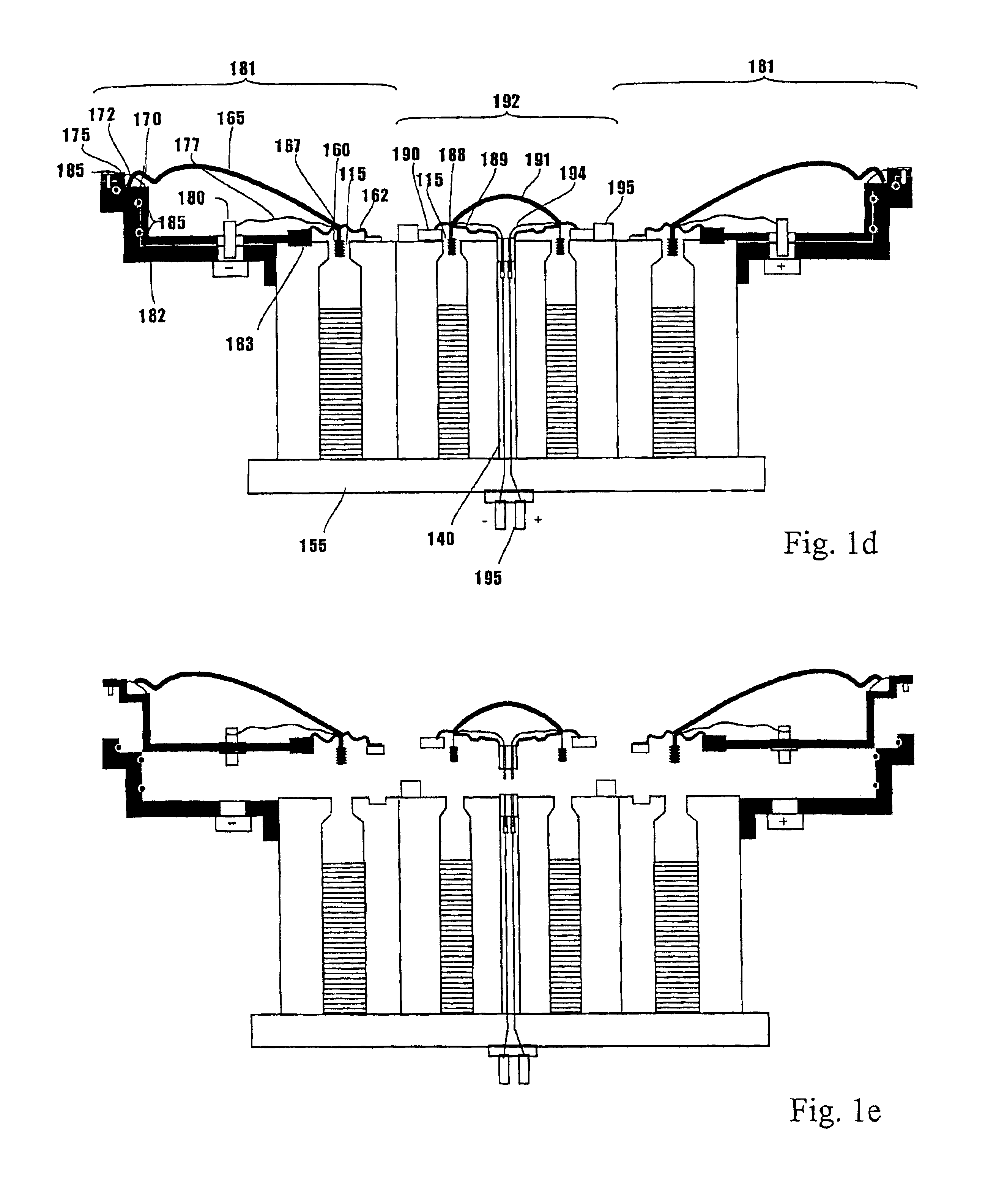
[0031]A first embodiment of the present invention will be described with reference to FIGS. 1a-e. Shown in FIGS. 1a-c are the magnetic circuits of a compound drive unit comprising two individual drive units for low frequency and high frequencies, respectively. A first outer pole piece 100 substantially formed as a hollow cylinder provides a first cylindrical center chamber, and has part of its inner surface in metallic contact with the outer surface of a first permanent magnet 105 of substantially cylindrical shape. A first inner pole piece 110 substantially formed as a hollow cylinder is with part of its outer surface in metallic contact with the inner surface of the permanent magnet 105 and constitutes together with the first pole piece 100 a pole gap 115. The first outer pole piece 100, the first permanent magnet 105 and the first inner pole piece 110 provides the magnetic circuit of the low frequency drive unit 120. Localized in the interior of, and co-axially and substantially ...


PUM


Abstract

A compound loudspeaker drive unit comprising a first drive unit and a second drive unit arranged co-axial with respect to the center axis of the loudspeaker, and each drive unit comprises permanent magnet means and pole piece means together forming a magnetic circuit with a pole gap for exciting a voice coil assembly, each pole gap providing magnetic field directed radially with respect to a center axis of the loudspeaker. At least one of the permanent magnet means has a radially extending magnetization direction with respect to said center axis of the loudspeaker and the acoustic centers of said drive units substantially coincide.

Description

CROSS-REFERENCE TO RELATED APPLICATIONS[0001]This patent application is related to and claims priority from the U.S. provisional patent application No. 60 / 257,693, filed Dec. 26, 2000, which hereby is incorporated by reference.TECHNICAL FIELD OF THE INVENTION[0002]The present invention relates electro-acoustic converters for sound reproduction, in particular, to compound loudspeaker drive units which have a multitude of functional units, are adapted to reproduce different part of the audio frequency spectra and are arranged in a co-axial and co-planar construction.BACKGROUND OF THE INVENTION[0003]In most loudspeaker system for reproducing a larger part of the audio frequency spectra at least two drive units are used. An example being a woofer used for reproduction of sounds in the low frequency bands and a tweeter used for the high frequency bands. The voice coils of the separate drive units are via a cross-over filter network connected to a power amplifier, which provide the electr...

Claims


Application Information

Patent Timeline
IPC IPC(8): H04R9/02H04R9/00H04R1/22H04R1/24H04R9/06
CPCH04R1/24H04R9/063H04R9/025H04R9/022
Inventor SAGREN, ANDERS
Owner SAGREN ANDERS
Why Eureka
Try Eureka