Compact evaporation apparatus

Inactive Publication Date: 2005-07-05
BOLTON DANNY R +1
View PDF10 Cites 48 Cited by
  • Summary
  • Abstract
  • Description
  • Claims
  • Application Information

AI Technical Summary

Benefits of technology

[0010]The present invention provides a compact evaporation apparatus having a series of vertically-stacked turbulence diverter plates within an evaporator vessel to optimize thermal efficiency. An influent level signal system is located outside the vessel

Problems solved by technology

In addition, water from rain and other sources percolates through the buried wastes, creating noxious leachates.
This process of disposal is itself regulated and expensive as evidenced by the large amount of attention that has been given to the transportation and safe disposal of industrial waste liquids.
A drawback of the Young apparatus is its complexity and inefficiency, and the apparatus does not produce the desirabl

Method used


Image

  • Compact evaporation apparatus
  • Compact evaporation apparatus
  • Compact evaporation apparatus

Examples


Embodiment Construction

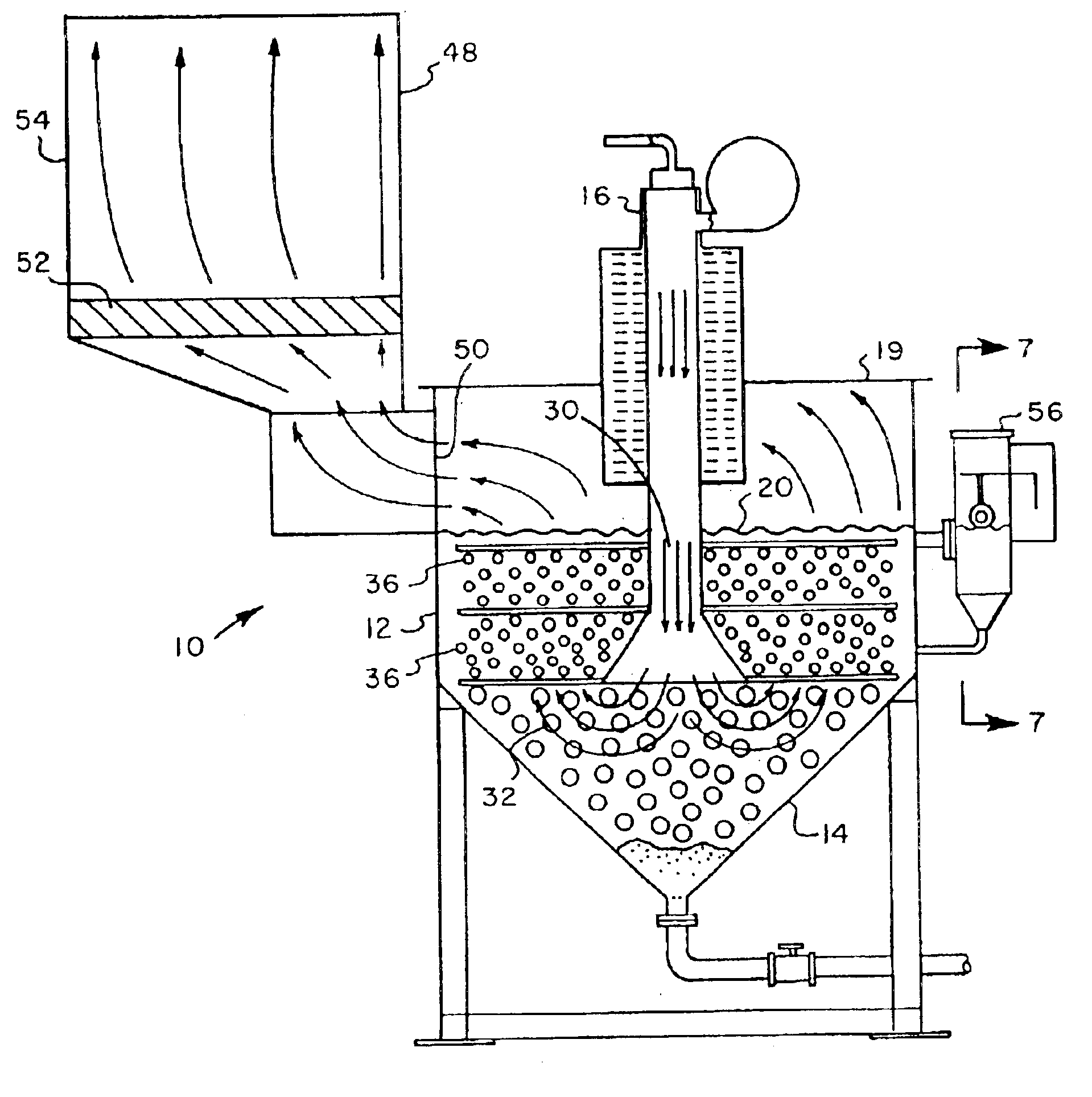
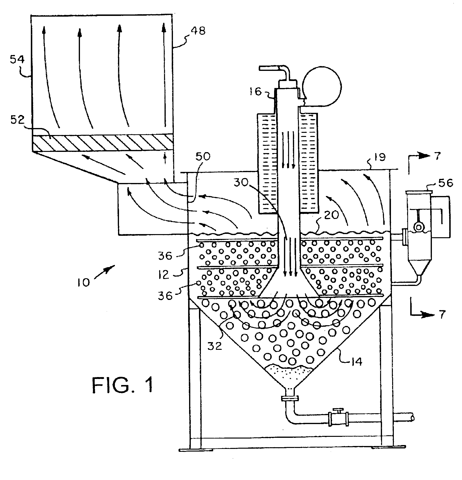
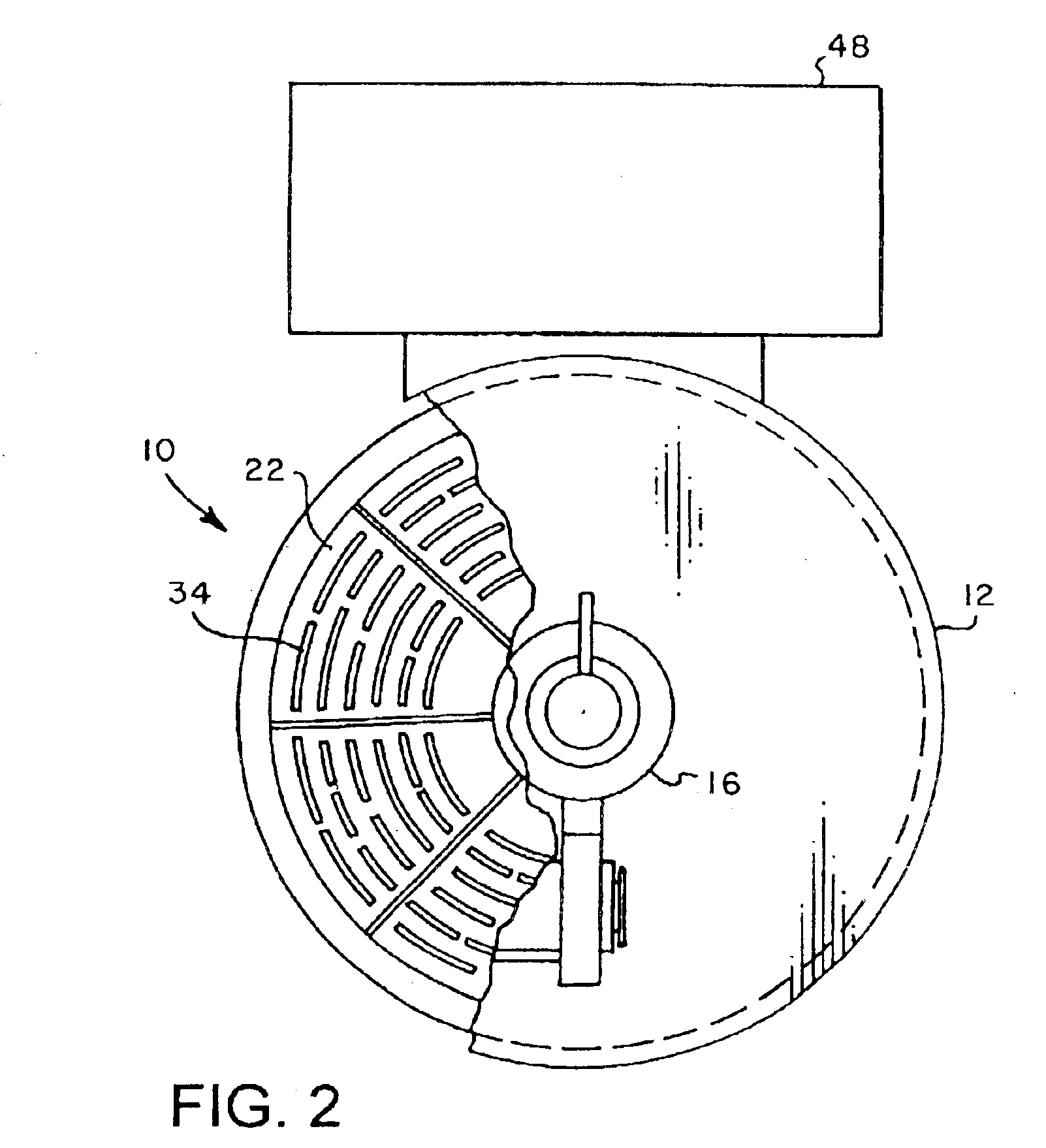
[0021]Referring initially to FIGS. 1-6, where like numerals indicate like and corresponding elements, compact evaporation apparatus 10 includes an evaporator vessel 12, which is cylindrical in form with a sloped, bottom chamber 14. While preferably the vessel 12 is cylindrical, a square or rectangular tank may also be used. Depending upon the corrosiveness of the liquid being processed, the vessel 12 may be manufactured from steel (stainless alloys and carbon) or a high temperature fiberglass. The fiberglass vessel 12 is to be used in high corrosion applications. All other submerged components used in a high corrosion application are of a highly corrosion-resistant stainless steel.

[0022]A burner 16 is mounted on top of, and fires into, a high temperature castable refractory-lined combustion chamber 18. Combustion chamber 18 extends through a top 19 of the vessel 12. The combustion chamber 18 is sized to achieve total combustion of the air / gas mixture from the burner 16 before being ...


PUM


Abstract

A compact evaporation apparatus includes an evaporator vessel with a sloped, bottom chamber. A combustion chamber is mounted to a top of the vessel, with a burner mounted to a top of the combustion chamber, the combustion chamber sized to achieve total combustion of an air/gas mixture supplied to the burner before being released below a liquid surface in the vessel. At least one turbulence diverter plate is located within the vessel beneath the liquid surface, the diverter plate being a submerged perforated plate extending horizontally from the combustion chamber, such that hot combustion gasses are released below the diverter plate, and as large gas bubbles rise to the surface they pass through small perforations in the diverter plate, thereby breaking large, hot gas bubbles into small bubbles, the gas to liquid contact area being maximized to increase system efficiency.

Description

BACKGROUND OF INVENTION[0001]1. Field of the Invention[0002]This invention relates to evaporators, and more particularly, to an evaporator for the treatment of contaminated wastewater.[0003]2. Background Art[0004]The disposal of contaminated wastewaters is of increasing concern due to ever tighter environmental regulations. Sources of such wastewaters are municipal landfills, petrochemical industries, paper industries, food industries, agricultural operations, remedial clean-up activities, and general industrial sources.[0005]In particular, various kinds of wastes are buried in landfills that are known to produce noxious gases and condensates as the wastes decompose. In addition, water from rain and other sources percolates through the buried wastes, creating noxious leachates. These leachates are composed of a variety of chemicals, many of which are hazardous Escaping gases and liquids from such landfills are recognized as sources of pollutants that present health and environmental...

Claims


Application Information

Patent Timeline
IPC IPC(8): B01D1/30B01D1/00C02F1/10C02F1/16
CPCB01D1/30B01D1/305C02F1/10C02F1/16Y10S159/02
Inventor BOLTON, DANNY R.BIGHAM, JAMES E.
Owner BOLTON DANNY R
Why Eureka
Try Eureka