
Thermoelectric power from environmental temperature cycles

Inactive Publication Date: 2005-07-05
HI Z TECH
View PDF5 Cites 67 Cited by
  • Summary
  • Abstract
  • Description
  • Claims
  • Application Information

AI Technical Summary

Benefits of technology

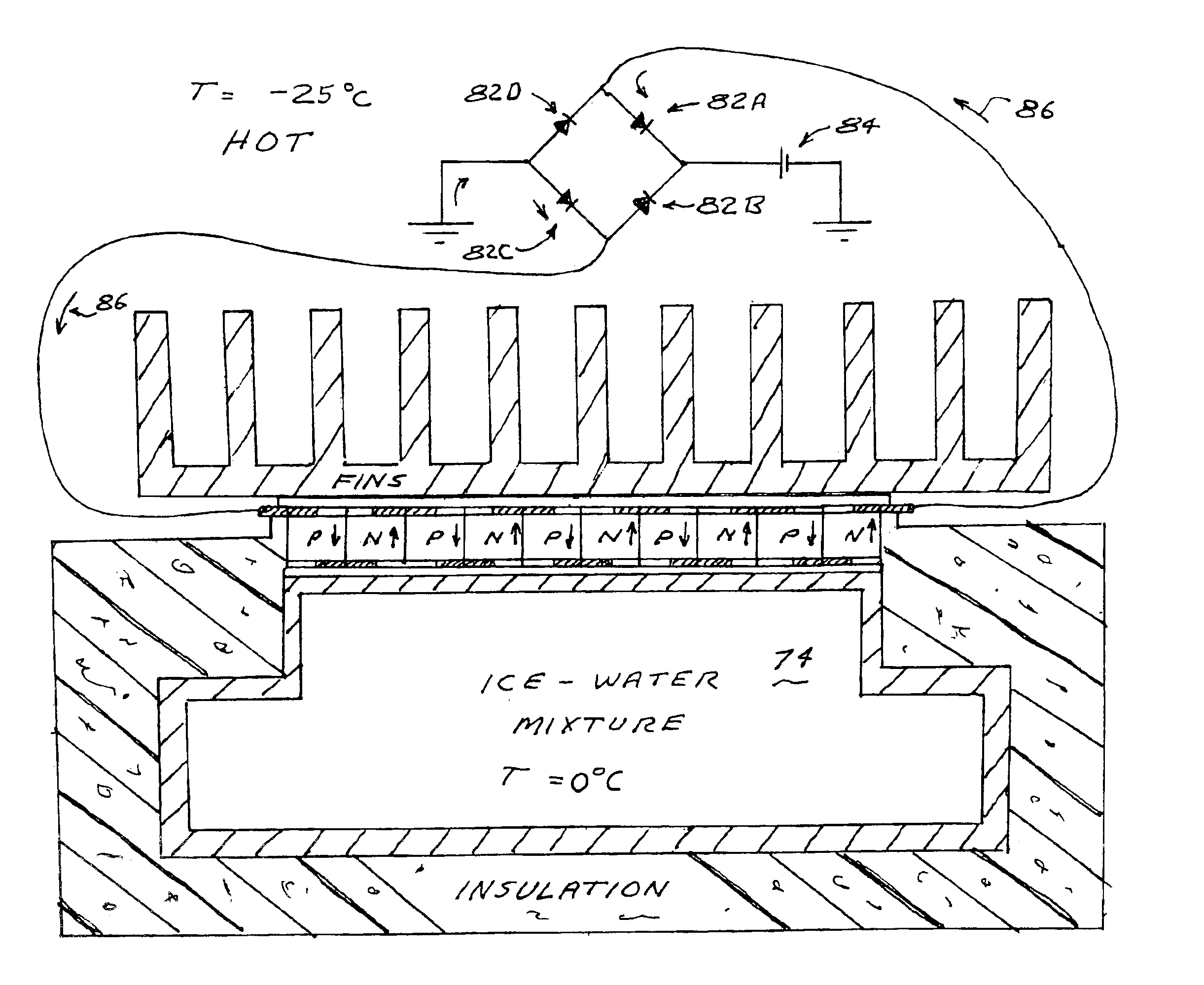
[0009]The present invention provides an electric generator system for producing electric power from the environmental temperature changes such as occur during a normal summer day on Earth or Mars. In a preferred embodiment a phase-change mass is provided which partially or completely freezes during the relatively cold part of a cycle and partially or completely melts during the relatively hot part of the cycle. A thermoelectric module is positioned between the phase-change mass and the environment. The temperature of the phase-change mass remains relatively constant throughout the cycle. During the hot part of the cycle heat flows from the environment through the thermoelectric module into the phase change mass generating electric power which is stored in an electric power storage device such as a capacitor or battery. During the cold part of the cycle heat flows from the phase change mass back through the module and out to the environment also generating electric power that also is similarly stored. An electric circuit is provided with appropriate diodes to switch the direction of the current between the hot and cold parts of the cycle. A preferred phase change mass is a solution of water and ammonia that has freeze points between about 270 K to about 145 K depending on the water ammonia ratio. Preferably, a finned unit is provided to efficiently transfer heat from a module surface to the environment.
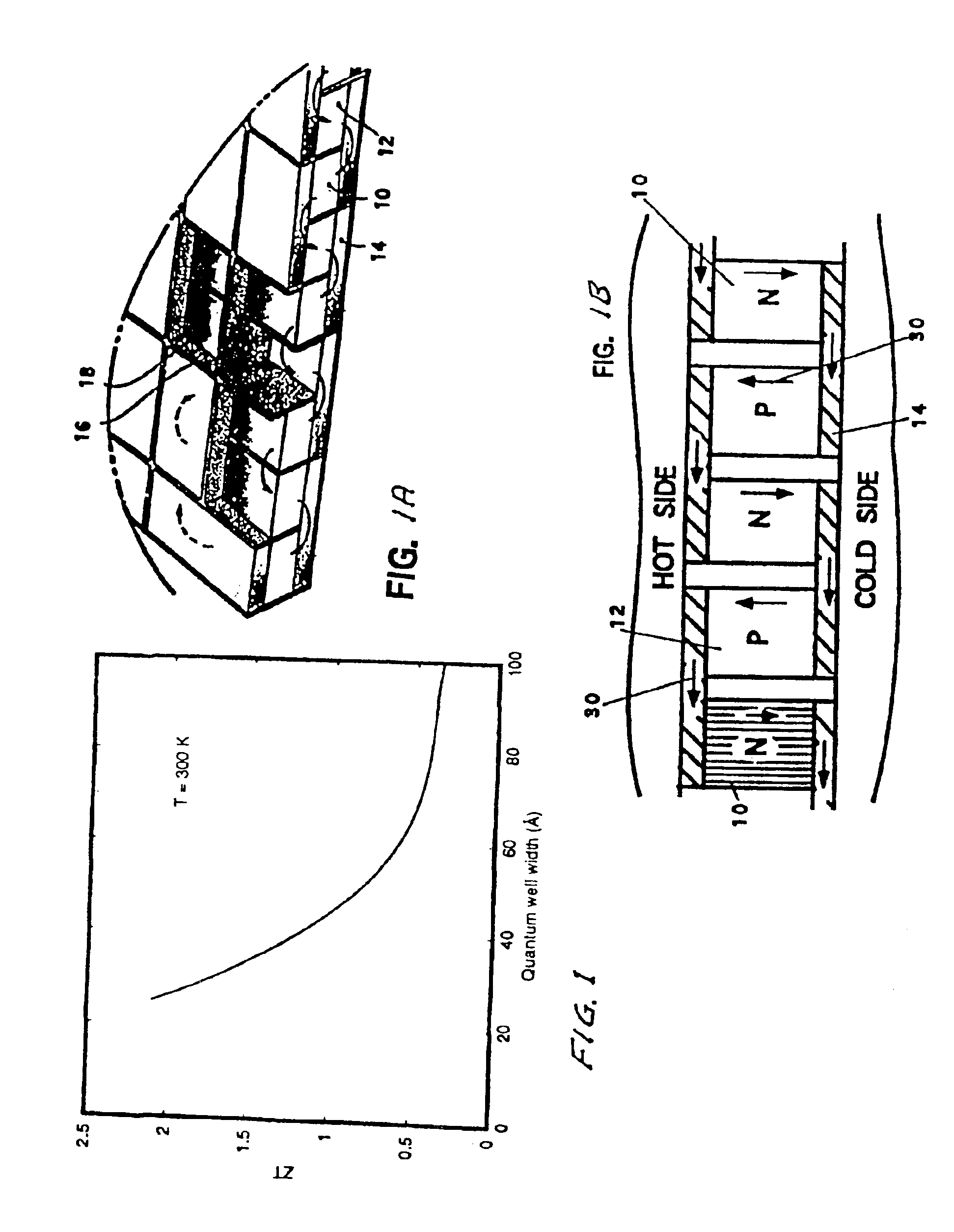
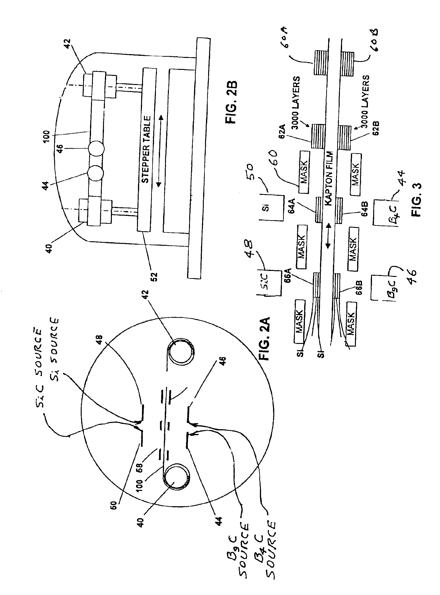
[0010]Many available thermoelectric modules could be used. Preferred modules for remote applications are those with good performance parameters and high reliability. Various types of modules are suggested. For highest module efficiencies quantum well modules are preferred with p-legs and n-legs, each leg being comprised of a large number of at least two different very thin alternating layers of elements. For applications where the temperature range is relatively low, such a Mars application, a preferred quantum well choice is n-doped Si / SiGe for the n-legs and p-doped Si / SiGe for the p-legs. At higher temperatures the preferred quantum well legs are alternating layers of silicon and silicon carbide for the n-legs and for the p-legs alternating layers of different stoichiometric forms of B-C.

Problems solved by technology

Workers in the thermoelectric industry have been attempting too improve performance of thermoelectric devices for the past 20-30 years with not much success.
Both technologies have advantages, however their disadvantages increase mission cost and decrease mission reliability.
RTG's are very reliable but have a high cost due to radioactive fuel production, encapsulation, and qualification.
There is also a cost associated with launch approval in accordance with the National Environmental Policy Act.
Solar cells have a much easier launch approval process, but they are not as reliable as RTGs.
If a solar cell array is improperly deployed or deployed facing the wrong direction on Mars then the mission could be hampered or fail.
Martian sandstorms can reduce the power of solar cells by the settling of dust on the array, and the wear of the cover glass as a result of abrasive sandstorms.

Method used


Image

  • Thermoelectric power from environmental temperature cycles
  • Thermoelectric power from environmental temperature cycles
  • Thermoelectric power from environmental temperature cycles

Examples


first preferred embodiment

[0029]A first preferred embodiment of the present invention is an energy-harvesting device that produces electrical power without fuel or sunlight. The device uses daily temperature variations of the Martian atmosphere to convert heat into electrical power using thermoelectric technology. The device is innovative because it does not require fuel or sunlight for operation. Unlike solar cells, the energy-harvesting device will not be vulnerable to Martian dust storms and high impact landings. Replacing nuclear generators with the energy-harvesting generator will reduce mission costs and increase safety of human missions because of the absence of nuclear fuel.

[0030]As shown in FIG. 9 this embodiment of the present invention utilizes a sphere for the basic shape of the generator because a sphere has the lowest surface area to volume ratio, thus it has minimal heat loss to volume ratio. A 1-foot diameter sphere for the generator is a reasonable dimension with a total weight of 3 pounds. ...


PUM


Abstract

An electric generator system for producing electric power from the environmental temperature changes such as occur during a normal summer day on Earth or Mars. In a preferred embodiment a phase-change mass is provided which partially or completely freezes during the relatively cold part of a cycle and partially or completely melts during the relatively hot part of the cycle. A thermoelectric module is positioned between the phase-change mass and the environment. The temperature of the phase-change mass remains relatively constant throughout the cycle. During the hot part of the cycle heat flows from the environment through the thermoelectric module into the phase change mass generating electric power which is stored in an electric power storage device such as a capacitor or battery. During the cold part of the cycle heat flows from the phase change mass back through the module and out to the environment also generating electric power that also is similarly stored. An electric circuit is provided with appropriate diodes to switch the direction of the current between the hot and cold parts of the cycle. A preferred phase change mass is a solution of water and ammonia that has freeze points between about 270 K to about 145 K depending on the water ammonia ratio. Preferably, a finned unit is provided to efficiently transfer heat from a module surface to the environment.

Description

[0001]This application is a continuation in part of Ser. No. 10 / 021,097 filed Dec. 12, 2001 now U.S. Pat. No. 6,828,579 which is incorporated herein by reference and also claims the benefit of Provisional Application Ser. No. 60 / 460,057 filed Apr. 3, 2003. The present invention relates to thermoelectric devices and in particular techniques for producing electric power from existing heat sources and to very thin lattice thermoelectric devices.[0002]This invention was made in the course of or under Contract Number N00178-03-C-3018 with the U.S. Naval Surface Warfare Center and the U.S. Government has rights under any patent resulting from this application.BACKGROUND OF THE INVENTION[0003]A well-known use for thermoelectric devices is for the extraction of electric power from waste heat. For example, U.S. Pat. No. 6,527,548 discloses a self powered space heater for a truck in which heat energy for the heater is used to power electric components of the heater plus charge a battery. In U...

Claims


Application Information

Patent Timeline
IPC IPC(8): H01L35/12H01L29/02H01L35/32H01L29/15H01L35/22
CPCH01L29/155H01L35/22H01L35/32H10N10/855H10N10/17
Inventor HILLER, NATHAN D.BASS, JOHN C.ALLEN, DANIEL T.
Owner HI Z TECH
Learn More