
Device and method for calibrating linear velocity and track pitch for optical disc drive

a linear velocity and optical disc technology, applied in the direction of digital signal error detection/correction, instruments, recording signal processing, etc., can solve the problems of inability to calibrate an optical disc drive, writing speed and track pitch during actual disc playing cannot be predicted, and wasting a long period of seeking tim

Inactive Publication Date: 2005-07-05
MEDIATEK INC
View PDF9 Cites 13 Cited by
  • Summary
  • Abstract
  • Description
  • Claims
  • Application Information

AI Technical Summary

Benefits of technology

The present invention provides a method for calibrating the linear velocity and track pitch of an optical disc drive. This method can be used for both blank and recorded discs, and can be applied to different control modes of the spindle motor. The calibration device includes a bit-clock generator, counter, and calculator, which generates data based on the motor frequency and the frequency of the bit-clock signal. The method involves initializing the drive, determining the type of disc, moving the laser beam to the lead-in area, calculating the first data amount, and then calculating the linear velocity and track pitch of the disc. The technical effects of this invention include high-precision calibration regardless of the type of disc and compatibility with different control modes of the spindle motor.

Problems solved by technology

However, the writing speed and track pitch during actual disc playing cannot be predicted.
However, the laser beam cannot be correctly and quickly shifted to the correct track in this method, thereby wasting a long period of seeking time.
This method, however, cannot calibrate an optical disc drive, which controls the spindle motor with a constant angular velocity (hereinafter referred to as CAV).
In addition, the prior art method can only calibrate the linear velocity with respect to optical discs having data recorded thereon, but not the blank discs.

Method used


Image

  • Device and method for calibrating linear velocity and track pitch for optical disc drive
  • Device and method for calibrating linear velocity and track pitch for optical disc drive
  • Device and method for calibrating linear velocity and track pitch for optical disc drive

Examples


Embodiment Construction

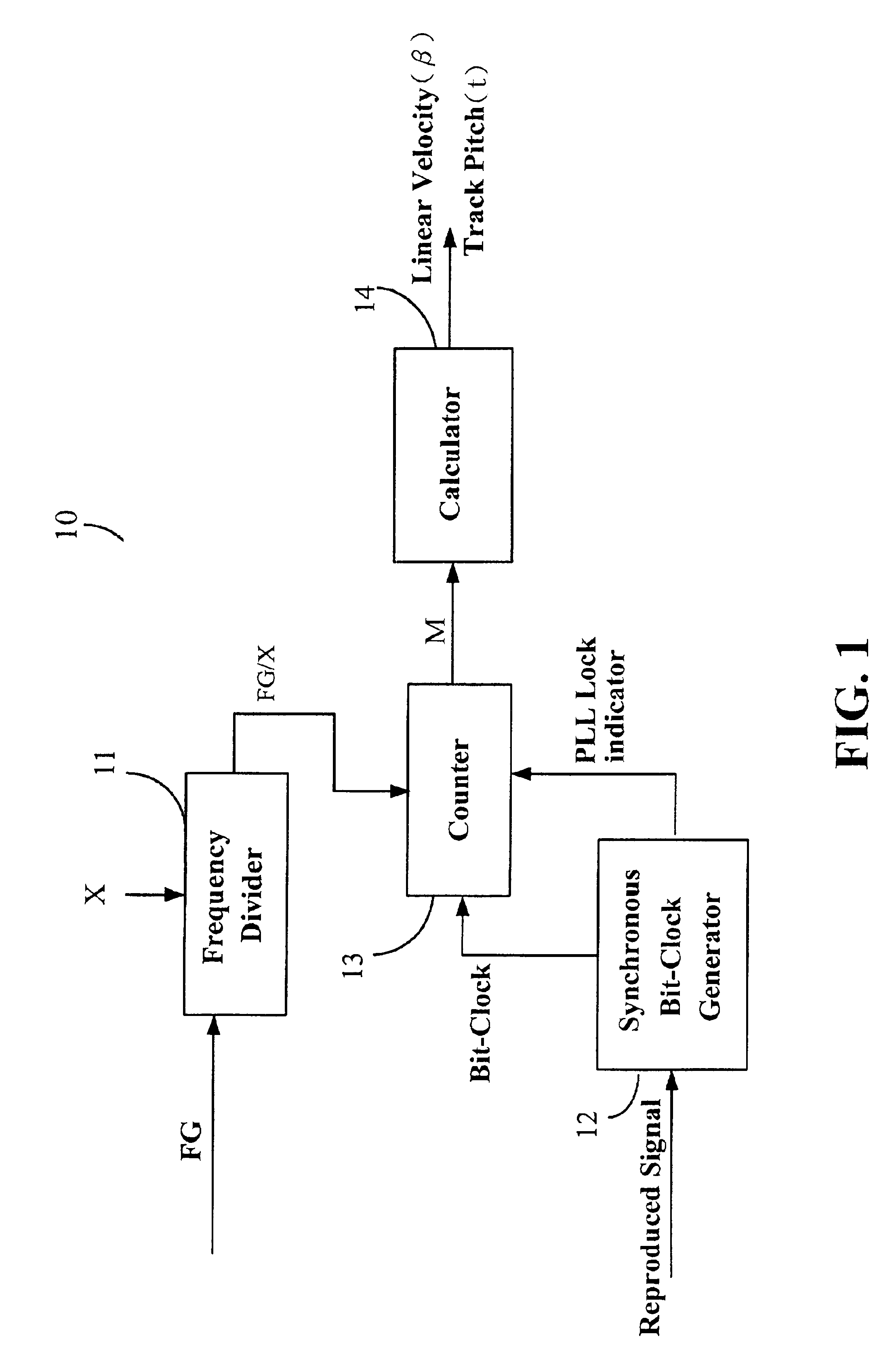
[0016]Two signals are used to compute the linear velocity in the present invention. The first signal is a frequency generator pulse (hereinafter referred to as a FG pulse), which is generated when the spindle motor in the optical disc drive rotates. The second signal is a playback signal or a reproduced signal, e.g., an EFM (eight-bit to fourteen-bit modulation) signal or a wobble signal read from an optical recording medium.

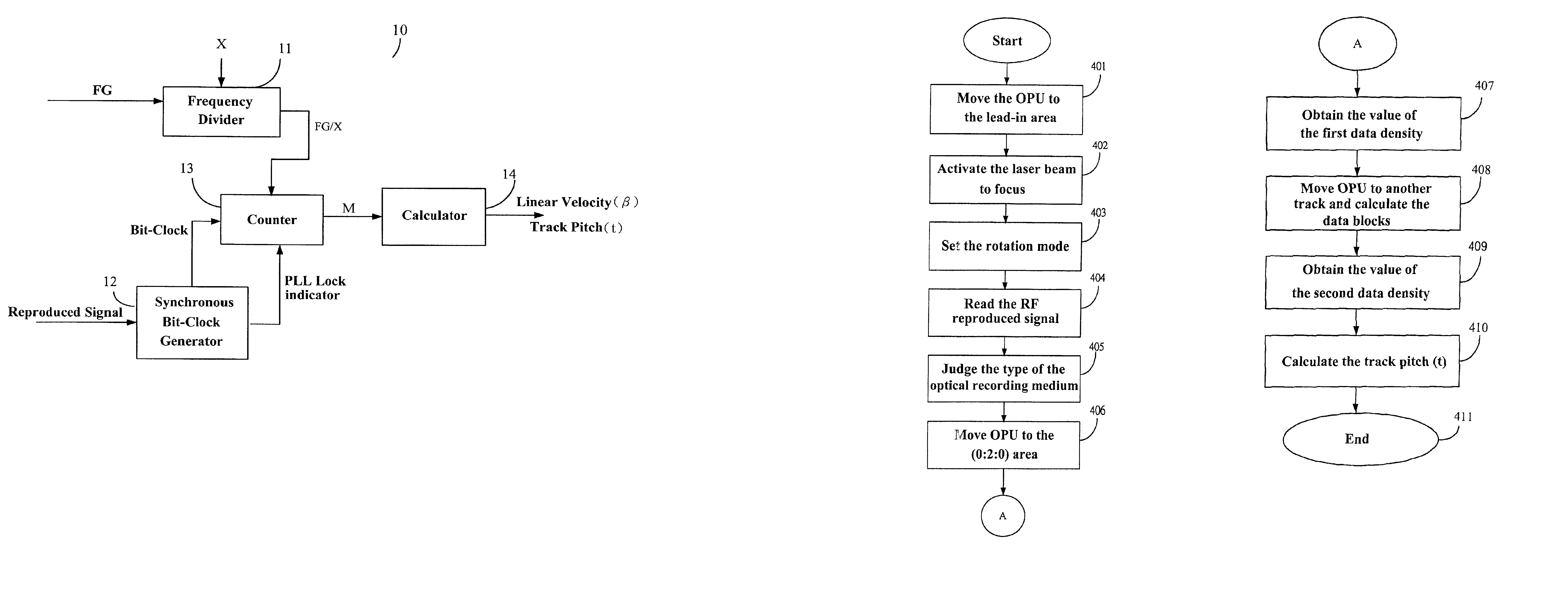
[0017]FIG. 1 is a block diagram showing a device for calibrating the linear velocity and track pitch of the present invention. As shown in the FIG. 1, a calibration device 10 includes a frequency divider 11, a synchronous bit-clock generator 12, a counter 13, a linear velocity and track pitch calculator 14.

[0018]The optical disc drive utilizes a motor speed controller (not shown) to control the rotation speed of the optical recording medium. The motor speed controller generates the FG pulses, for example 6 pulses per rotation of the spindle motor. The frequency ...


PUM

PropertyMeasurementUnit
radiusaaaaaaaaaa
recording linear velocityaaaaaaaaaa

Abstract

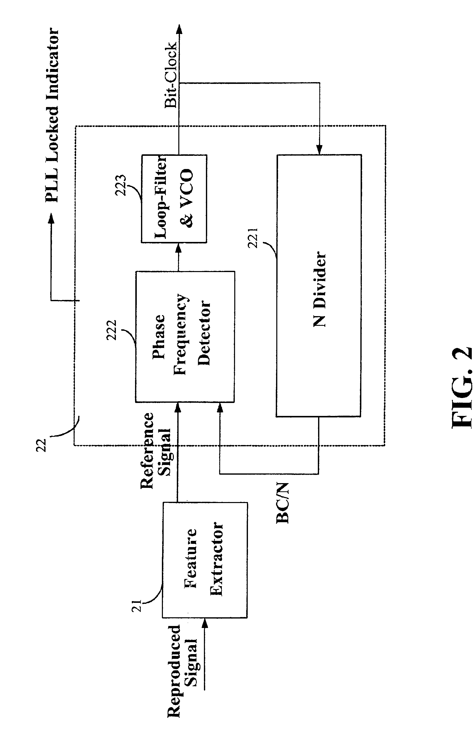
A device and method for calibrating linear velocity and track pitch for an optical disc is disclosed. The device comprises a frequency divider, a synchronous bit-clock generator, a counter and a linear velocity and track pitch calculator. The frequency divider receives a motor frequency generator (FG) pulse and generates a motor rotation period signal (FG / X). The synchronous bit-clock generator generates a high frequency bit-clock according to a reproduced signal read from disc. The bit counter counts the pulse of the bit-clock for each period of the motor rotation period signal to generate the data amount M. The linear velocity and track pitch calculator calculates the linear velocity by a linear velocity function with the information of the data amount M and the motor rotation period. Then, the linear velocity and track pitch calculator calculates the track pitch by a pitch function with the information of the data amount, radius and linear velocity at different tracks.

Description

BACKGROUND OF THE PRESENT INVENTION[0001]A. Field of the Present Invention[0002]The present invention relates to a device and method for calibrating a linear velocity and a track pitch for an optical disc drive.[0003]B. Description of the Related Art[0004]Optical recording media, such as CD-Rs, CD-RWs, CD-ROMs, DVDs, DVD-RAMs, are usually read by optical disc drives. These optical disc drives correctly control the rotation speed of the spindle motor according to a reproduced sync signal or a motor frequency generator pulse signal. In addition, a precise calculation has to be performed using a “time-to-track” transformation mechanism, so that the laser beam can be shifted to a correct position of the disc (i.e., track jumping). The mechanism of “time-to-track” has to use the parameters of the linear velocity and the track pitch as a calculation basis. According to the current CD standard, the recording linear velocity must be between 1.2 and 1.4 m / s, while the track pitch must be bet...

Claims


Application Information

Patent Timeline
Patent Type & Authority Patents(United States)
IPC IPC(8): G11B7/005G11B7/00G11B7/085G11B27/24G11B27/30
CPCG11B27/24G11B27/3027G11B7/0053G11B7/08529
Inventor TSAI, CHAO-LONGHO, CHI-KWONGHSU, JIN-CHUAN
Owner MEDIATEK INC
Learn More