Method for assembling conductive segments of a rotor winding or stator winding in a rotary electric machine

a technology of rotary electric machines and conductive segments, which is applied in the direction of manufacturing winding connections, magnets, magnets, etc., can solve the problems of increasing production costs, limiting the quantity of heat released outside the welding zone, and difficult to envisage high-speed production lines, etc., to achieve rapid, simple and economical assembly, and reduce the cost of segments. , the effect of high quality

Inactive Publication Date: 2005-07-12
VALEO EQUIP ELECTRIC MOTEUR
View PDF8 Cites 19 Cited by
  • Summary
  • Abstract
  • Description
  • Claims
  • Application Information

AI Technical Summary

Benefits of technology

[0016]It is thus no longer necessary to provide a preliminary stripping stage, such as, for example, mechanical stripping of the layer of electrically insulating material. Moreover, the outlay incurred for the assembly of the segments is considerably reduced. The solution is thus rapid, simple and economical.
[0017]Surprisingly, it has furthermore been found that when the welding process used is a welding process of the electron-beam or laser type, welds of very high quality can be achieved without carrying out preliminary stripping of the conductive segments or welding in the presence of residues of electrically insulating materials when a preliminary stage of partial stripping is implemented, that is to say without spoiling the conductive wire.
[0025]the welding process is an accurate and rapid laser-welding process which makes it possible to obtain penetrating seams of high geometrical accuracy.

Problems solved by technology

This limits the quantity of heat released outside the welding zones.
However, this technique has one major disadvantage, inasmuch as it requires preliminary stripping of the free ends of the conductive segments to be welded, considerably increasing the costs of production, and is difficult to envisage in high-speed production lines inasmuch as the stripping operation takes a relatively long time.
Moreover, when the stripping stage is performed mechanically, in order to completely remove the layer of electrically insulating material, the peripheral surface of the conductive wire is inevitably cut, leading to a reduction in the useful cross section of the conductive segments.

Method used


Image

  • Method for assembling conductive segments of a rotor winding or stator winding in a rotary electric machine
  • Method for assembling conductive segments of a rotor winding or stator winding in a rotary electric machine
  • Method for assembling conductive segments of a rotor winding or stator winding in a rotary electric machine

Examples


Embodiment Construction

OF THE INVENTION

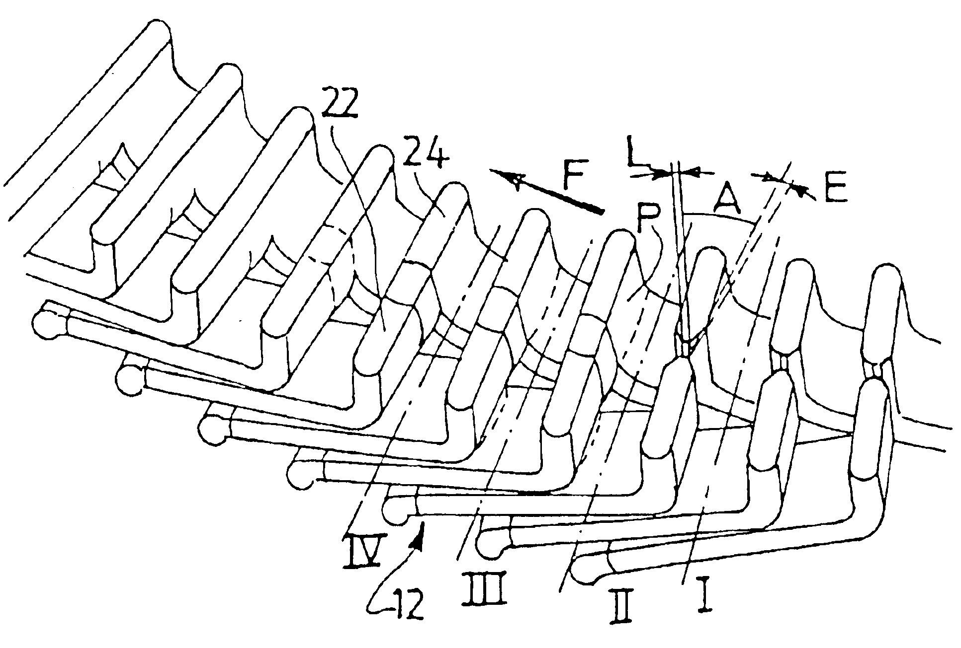
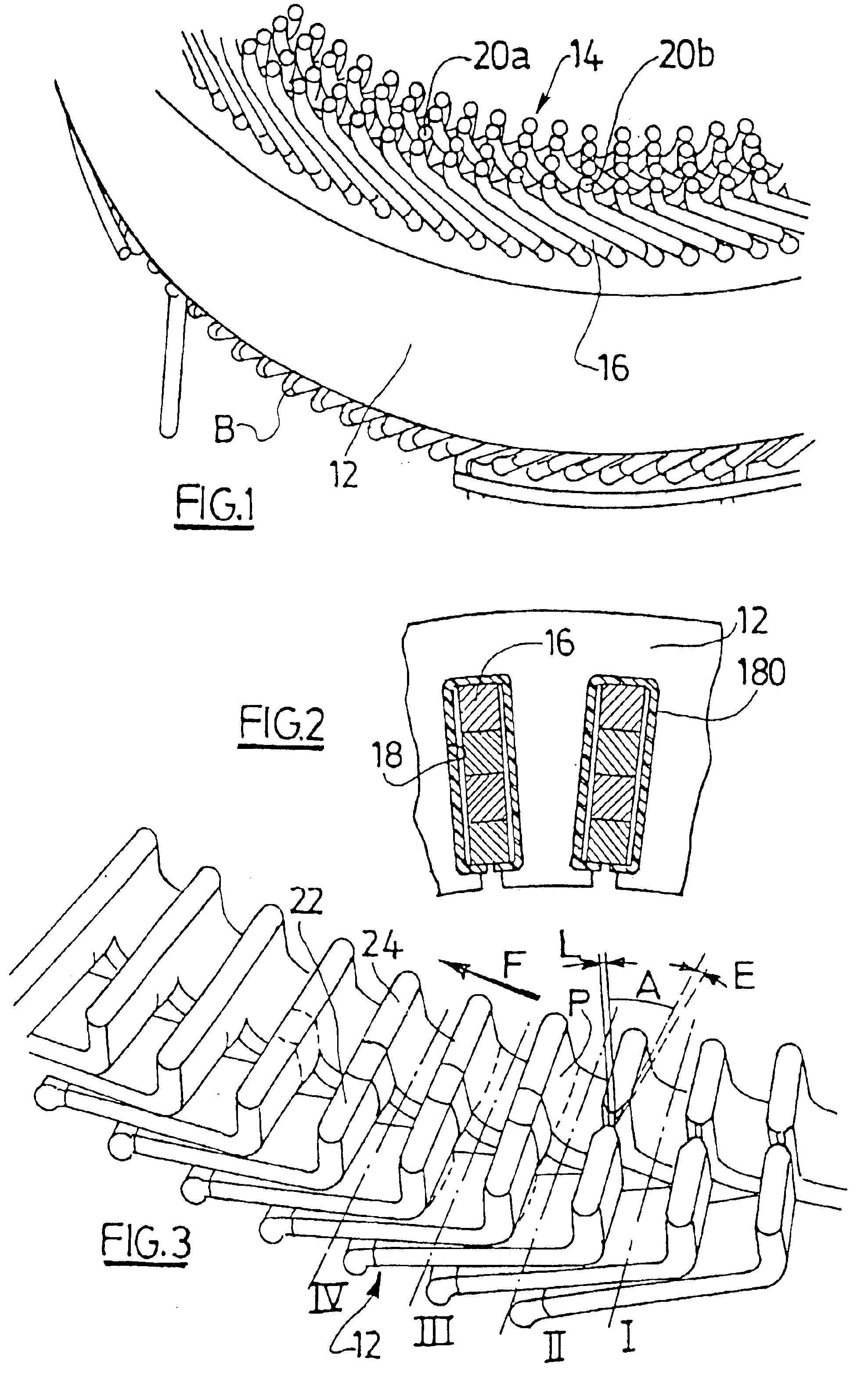
[0040]In the explanation which follows, the assembly of a stator winding of a motor-vehicle alternator will be described. However, the invention also applies, where appropriate, to the assembly of a rotor winding of an alternator and, in a general way, to the assembly of a rotor or a stator of a rotary electrical machine.

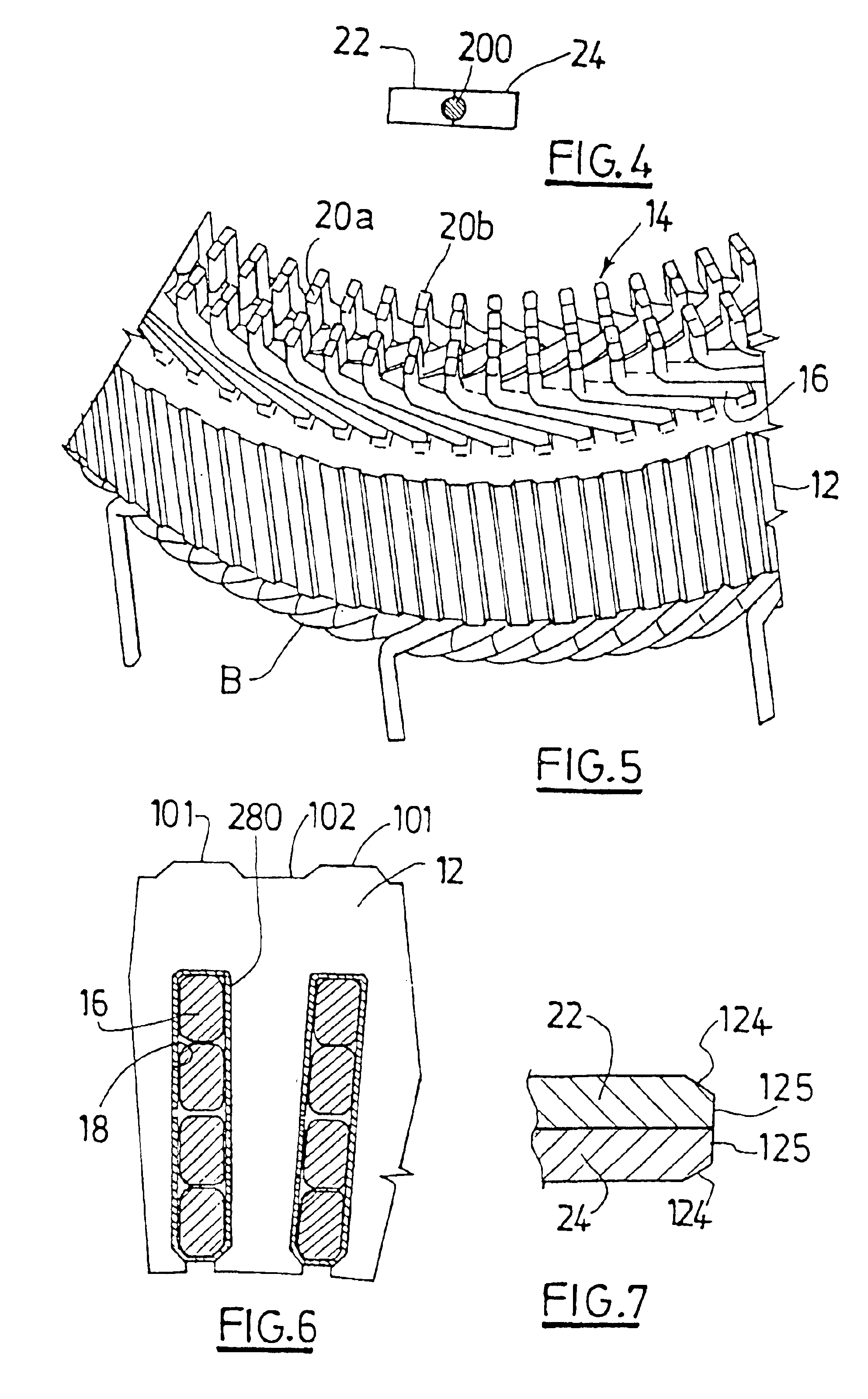
[0041]As is known, a conventional motor-vehicle alternator includes a rotor firmly fixed to a rotor shaft, the axial ends of which are supported in rotation by a hollow support designed to be mounted on a fixed part of the motor vehicle. On the inside, at its outer periphery, this support carries a stator, described below, surrounding the rotor. In this alternator, the rotor is shaped to form an inductor, while the stator is shaped to form an armature.

[0042]The support includes two parts, referred to respectively as a front bearing and a rear bearing. Each bearing features a central receptacle for mounting a ball bearing, in which the relevant end of...


PUM

PropertyMeasurementUnit
angleaaaaaaaaaa
widthaaaaaaaaaa
conductiveaaaaaaaaaa

Abstract

This process for assembling conductive segments (16) of a rotor or stator winding of a rotary electrical machine comprises the stages consisting in inserting the conductive segments (16) in slots arranged in a core (12) of the rotor or of the stator in such a way that the conductive segments project beyond the latter by their free ends, and in welding the conductive segments in pairs by their projecting free ends to form a winding (14) around the rotor or the stator.The conductive segments each being formed by a wire of electrically conductive material covered with a layer of electrically insulating material, the layer of electrically insulating material is eliminated, in the zone in which the conductive segments are welded, by the means used to weld the latter.Application to the assembly of conductive segments of a rotor or stator winding of a motor-vehicle alternator.

Description

[0001]This application is the U.S. National Phase under 35 U.S.C. 371 of International Application PCT / FR02 / 00719, filed Feb. 28, 2002.FIELD OF THE INVENTION[0002]The present invention relates to a process for assembling conductive segments of a rotor or stator winding of a rotary electrical machine.[0003]More particularly, the invention concerns a process for assembling conductive segments of a rotor or stator winding of a motor-vehicle alternator.PRIOR ART[0004]In a conventional configuration, the stator windings of a motor-vehicle alternator are formed by using pre-formed conductive winding segments in the form of a U, which are inserted, by their base, into slots formed in a core of the stator in such a way that the mutually opposite free-end zones of the conductive segments project beyond the latter, and by welding the conductive segments in pairs to form continuous wound components around the core.[0005]An assembly technique of this kind is described, for example, in the docum...

Claims


Application Information

Patent Timeline
Patent Type & Authority Patents(United States)
IPC IPC(8): H02K15/00H02K3/04H02K3/12H02K15/08
CPCH02K15/0056H02K15/0081Y10T29/49071Y10T29/53143Y10T29/49009Y10T29/49012Y10T29/49011H02K3/12
Inventor LENOIR, ROMARICARRIGHI, SEBASTIENEVEN, DENISHEVIA, THIERRY
Owner VALEO EQUIP ELECTRIC MOTEUR
Why Eureka
Try Eureka