Muffler device

a technology of muffler and muffler body, which is applied in the direction of exhaust treatment, gas passage, gas chamber, etc., can solve the problems of small volume of unignited fuel present in the muffler, unignited fuel to accumulate in such regions, and range from annoying to potentially dangerous, so as to reduce the sound-attenuating capacity of the muffler and reduce the enhanced engine performance produced by the muffler. , the effect of economical manufactur

Inactive Publication Date: 2005-07-12
KHAYALIAN GARABED
View PDF36 Cites 8 Cited by
  • Summary
  • Abstract
  • Description
  • Claims
  • Application Information

AI Technical Summary

Benefits of technology

[0009]In particular, it is an object of the present invention to provide a sound-attenuating muffler for an internal combustion engine or the like, and method, which prevents the accumulation of unignited fuel in low-pressure volumes in the muffler without significantly decreasing the sound-attenuating capacity of the muffler.
[0010]It is another object of present invention to provide a sound-attenuating muffler and method which prevents accumulation of unignited fuel in the muffler without decreasing the enhanced engine performance produced by the muffler.
[0011]It is a further object of the present invention to provide a sound-attenuating muffler which prevents accumulation of unignited fuels in the muffler, yet is still compact and durable, has a minimum number of components and is economical to manufacture.
[0012]In keeping with the principles of the present invention, a unique muffler is herein disclosed having a first, second, third and fourth barrier in one preferred embodiment. Each barrier functions to form a compartment within which the exhaust stream can be partitioned and redirected. Eventually, the exhaust streams are once again recombined and expelled from the muffler. The partitioning and reassembly of the exhaust streams provides sound attenuation while increasing the horsepower of the engine and without resulting in any build up of unignited fuel.

Problems solved by technology

When these exhaust components reach the muffler, the muffler partitions typically quench or retard further burning of unignited fuel rather quickly.
The result is that a small volume of unignited fuel may be present in the muffler.
If the muffler includes low-pressure regions or volumes, there will be a tendency for this unignited fuel to accumulate in such regions.
The accumulation of unignited fuels in mufflers having low-pressure volumes can present a problem which ranges from annoying to potentially dangerous.
However, under some conditions explosive detonations or rapid combustion can occur.
Such muffler explosions can range from disconcerting popping sounds during deceleration to violent explosions which damage the muffler and exhaust system.

Method used


Image

  • Muffler device
  • Muffler device
  • Muffler device

Examples


Embodiment Construction

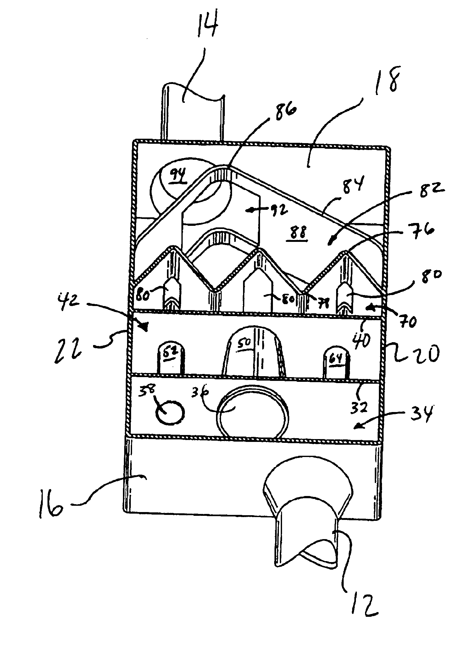
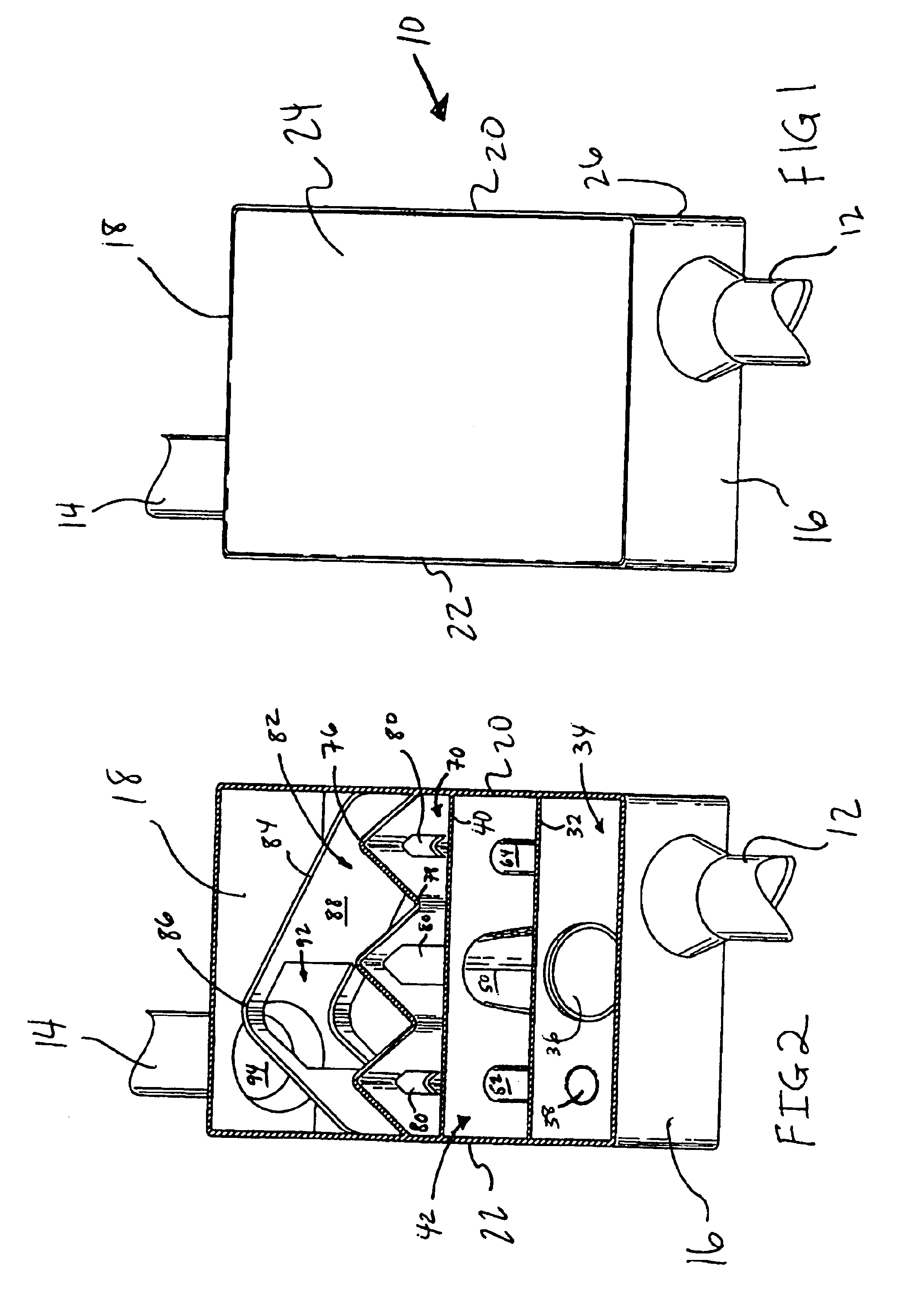
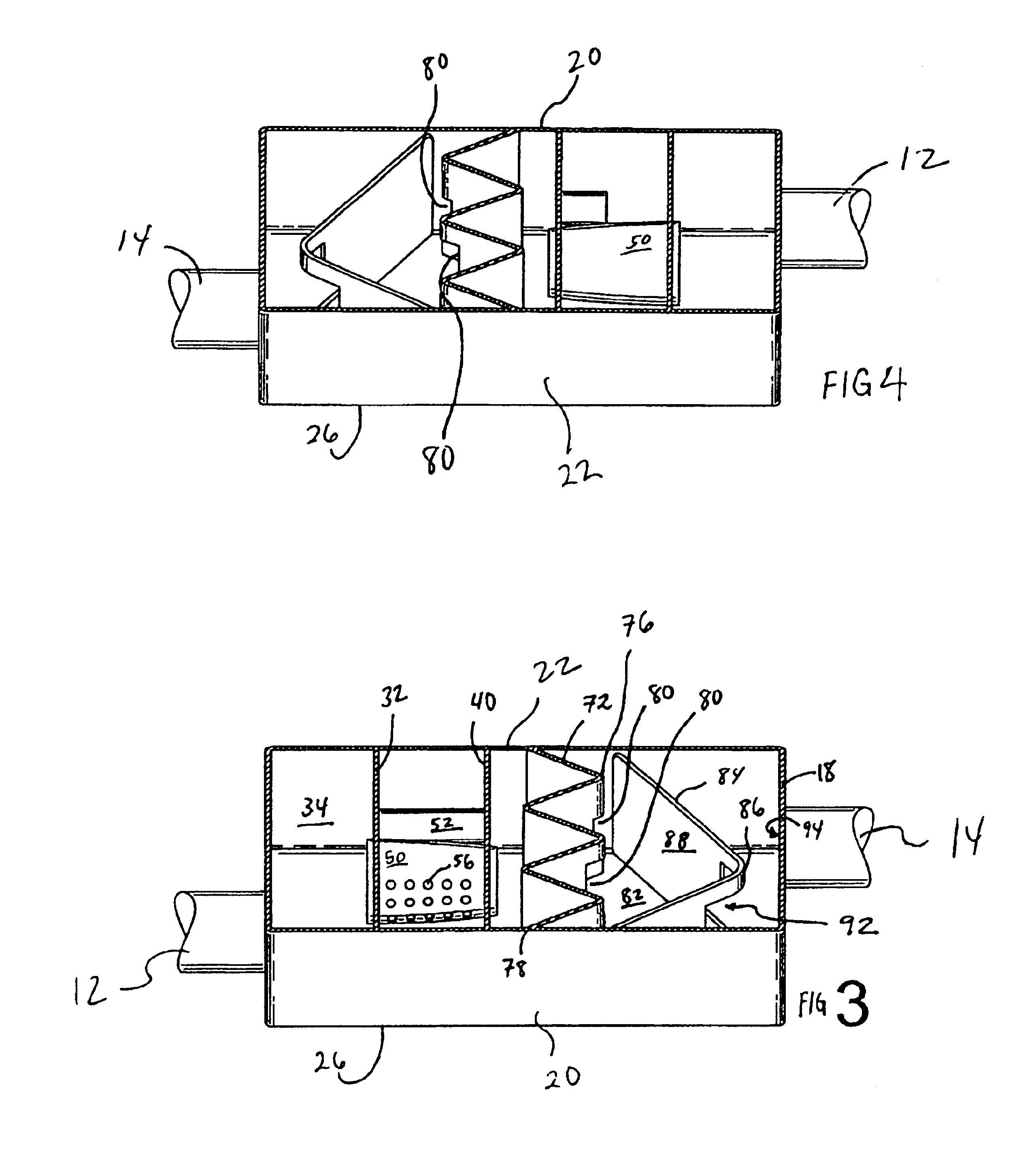
[0023]Referring to FIGS. 1 through 4, therein is illustrated a muffler device generally designated by the number 10 and having a generally rectangular shape. However, it is to be understood that the shape of device 10 may be altered without departing from the essence of the invention. In addition, the materials described and the dimensions given can be modified to accommodate different engines and physical requirements of other types of vehicles with which device 10 may be used. Device 10 has an inlet conduit 12 and an outlet conduit 14 attached to an inlet wall 16 and an outlet wall 18 respectively, through which walls said conduits 12 and 14 traverse and allow communication there through. Inlet wall 16 and outlet wall 18 are interconnected by a first sidewall 20 and a second sidewall 22. A top 24 and a bottom 26 extend over walls 16, 18, 20, and 22 on opposing sides thereof and enclose the same.

[0024]Now also referring to FIGS. 5 through 7, arrow 28 illustrates incoming exhaust pu...


PUM


Abstract

A muffler device, in one preferred embodiment, having four barriers therein. Each barrier functions to form an within which the exhaust stream can be partitioned and redirected. Eventually, the exhaust streams are once again recombined and expelled from the muffler. The partitioning and reassembly of the exhaust streams provides sound attenuation while increasing the horsepower of the engine and without resulting in any build up of unignited fuel.

Description

FIELD OF THE INVENTION[0001]The present invention relates to the field of mufflers for internal combustion engines in general, and specifically to mufflers in which sound attenuation is achieved with a minimum back-pressure thereby resulting in increased engine horsepower.BACKGROUND OF THE INVENTION[0002]Mufflers have been developed for the attenuation of the sound component in an exhaust gases from an internal combustion engine which employ sound-attenuating partition configurations that produce low-pressure regions or volumes within the muffler. The low-pressure volume can be the result of cancellation of identical sound frequencies by directing streams of gas to collide against each other, or can be the result of fluid flow patterns through the muffler, or both.[0003]The flow of exhaust gases through a muffler is not in a steady stream of the type which exits a garden hose. Instead, each time an exhaust valve opens, a pulse of exhaust gases is discharged into the exhaust system. ...

Claims


Application Information

Patent Timeline
Patent Type & Authority Patents(United States)
IPC IPC(8): F01N1/06F01N1/08
CPCF01N1/06F01N1/083F01N1/089F01N2260/06F01N2470/02F01N2490/04F01N2490/08F01N2490/16
Inventor KHAYALIAN, GARABED
Owner KHAYALIAN GARABED
Why Eureka
Try Eureka