Apparatus and method for cannulating retinal blood vessels

Inactive Publication Date: 2005-07-12
JNW PARTNERS
View PDF17 Cites 20 Cited by
  • Summary
  • Abstract
  • Description
  • Claims
  • Application Information

AI Technical Summary

Benefits of technology

[0017]If the illumination is incorporated within the infusion line and infusion cannula then the illumination/infusion line may be placed into a illumination positioner that can be mounted on the stabilization post attached to the surgical wrist-rest. The illumination positioner may be adjustable in the x, y and z planes such that the angle of the fiber optic illumination relative to the eye may be set. This is beneficial in directing the light to the area of the retina that the surgeon is working on.
[0018]In another embodiment of the microcannula, a sheath protects the shaft of the microcannula and/or a cover protects the tip of the microcannula during insertion into the eye. Once the microcannula is within the eye the cover is retracted thus exposing the tip. The cover may be slid over the microcannula tip prior to removing the device from the eye in order to mini

Problems solved by technology

The cannulation of a retinal blood vessel is difficult as the lumen of the blood vessels is less than 200 microns in size.
The present day ocular instruments a

Method used


Image

  • Apparatus and method for cannulating retinal blood vessels
  • Apparatus and method for cannulating retinal blood vessels
  • Apparatus and method for cannulating retinal blood vessels

Examples


first embodiment

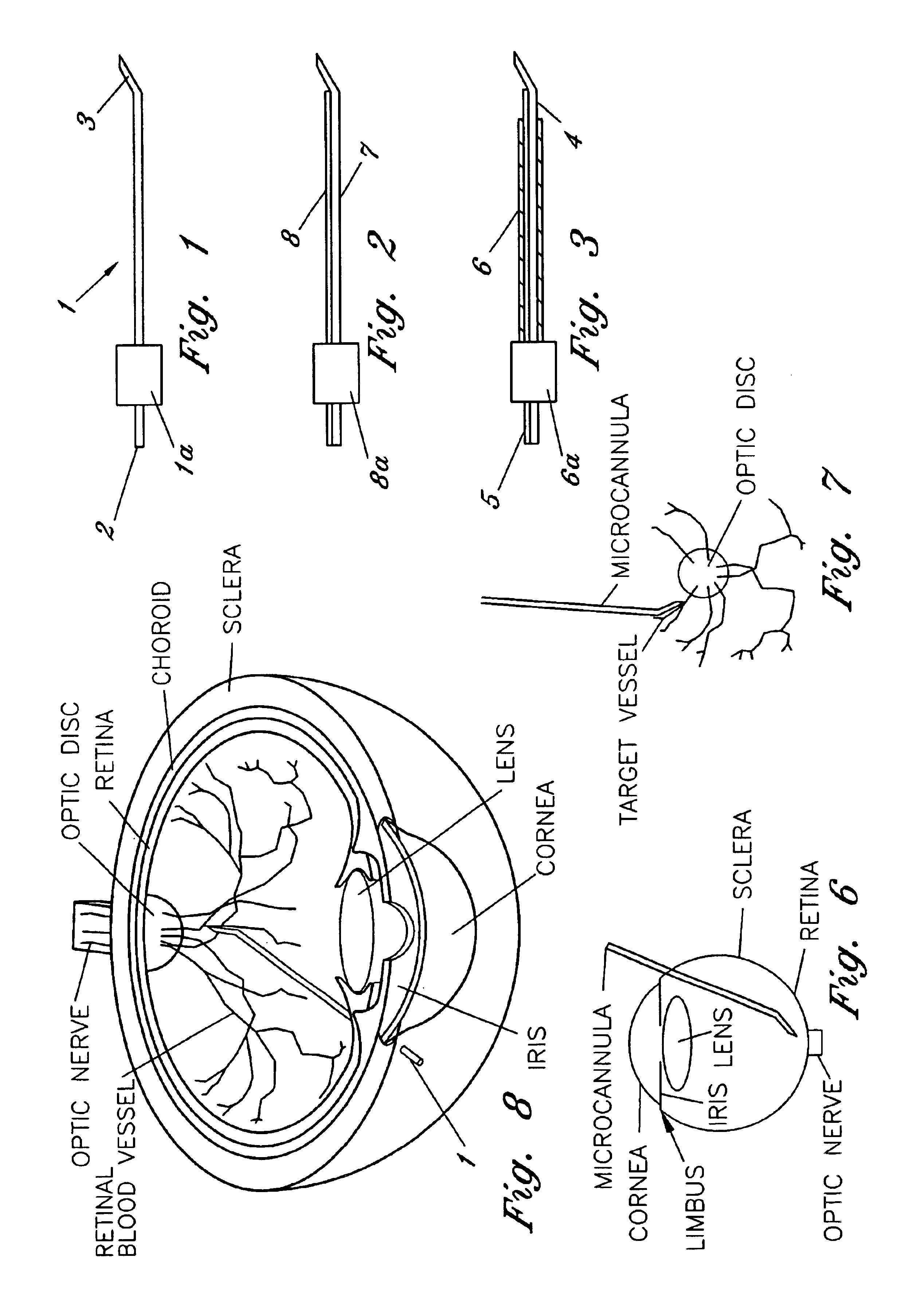
[0042]FIG. 1 illustrates a first embodiment for the micropipette / microcannula (1) showing the opening (2) that is preferably connected to a surgical tubing and the tip (3) of the micropipette oriented at an approximately 135 degree angle, although other ranges are possible. Tip (3) is angled so that it may safely cannulate the retinal vessel when micropipette (1) is placed through a standard retinal surgical sclerotomy site. While glass is suggested for the material because of its ease of fashioning, strength, transparency, etc., other materials may be used. It is essential, however, that the materials maintain substantial strength when fashioned to perform retinal vessel cannulation. A handle (1a) is shown attached to the body member of micropipette (1). Handle (1a) fits securely within a micropipette holder (10) by inserting the end of micropipette (1) associated with handle (1a) and handle (1a) into the front opening of holder (10). Once inserted micropipette (1) is held in place...

fourth embodiment

[0051]FIGS. 9A and 9B illustrate a front view of the microcannula in which the shaft (7) of the microcannula is enclosed by a protective sheath (6).

fifth embodiment

[0052]FIGS. 10A and 10B illustrate a fifth embodiment for the microcannula showing the microcannula (7) within a protective sheath (6) that protects the shaft of the microcannula and protective cover (31) that protects the tip of the microcannula (FIG. 10A). The protective sheath and cover may be made of metal, plastic, or other materials that protects the shaft and tip of the microcannula. As seen in FIG. 10B, the cover may be retracted once the microcannula is within the eye and is replaced or extended outwards once the procedure is complete and the microcannula is ready for removal from the eye, such that tip breakage is minimized.


PUM


Abstract

An apparatus and method for safely cannulating a retinal blood vessel is described. The apparatus consists of a micropipette/microcannula, micromanipulator and positioner mounted to a base, which is attached to a wrist rest commonly used in eye surgery. The micropipette/microcannula is connected to tubing such that a medication may be injected through the micropipette/microcannula into the blood vessel or conversely, a small quantity of material may be removed from a blood vessel. Alternatively, a catheter, wire or stent may be placed through the micropipette/microcannula to treat or diagnose an area remote from the insertion site. The ability to cannulate a retinal blood vessel should be efficacious in the treatment of vein and artery occlusion, ocular tumors and other retinal, vascular and optic nerve disorders that would benefit from diagnosis and/or treatment.

Description

CROSS-REFERENCE TO RELATED APPLICATIONS[0001]This application is a continuation-in-part of U.S. application Ser. No. 09 / 109,454, filed Jul. 2, 1998. This invention was disclosed in the Disclosure Documents Program of the U.S. Patent and Trademark Office on May 4, 1998, Disclosure Document No. 435938.BACKGROUND OF THE INVENTION[0002]1. Field of the Invention[0003]This invention relates to medical diagnostic and therapeutic methods and, in particular, to a method for cannulating a retinal blood vessel such that a medication may be injected or a quantity of fluid removed from the blood vessel. Alternatively, a catheter, wire or stent may be placed through the cannula to treat or diagnose an area remote from the insertion site.[0004]2. Description of Related Art[0005]The cannulation of a retinal blood vessel is difficult as the lumen of the blood vessels is less than 200 microns in size. The present day ocular instruments are too large to cannulate the vessel and the dexterity required ...

Claims


Application Information

Patent Timeline
IPC IPC(8): A61F9/00A61F9/007A61M25/00A61F2/06A61F2/82
CPCA61F9/0017A61F9/007A61M25/00A61F2/82A61F9/00709A61M2025/0042A61M2210/0612
Inventor WEISS, JEFFREY N.
Owner JNW PARTNERS
Why Eureka
Try Eureka