Combustion gas burner enabling multi-stage control

a combustion gas burner and multi-stage technology, applied in the direction of burners, combustion regulation, combustion types, etc., can solve the problems of increasing the loss of heat due to high-temperature exhaust gas, needing more than the theoretical amount of air, and increasing the amount of pollutants, so as to facilitate the change of the burner design

Inactive Publication Date: 2005-07-12
KYUNGDONG NAVIEN +1
View PDF8 Cites 16 Cited by
  • Summary
  • Abstract
  • Description
  • Claims
  • Application Information

AI Technical Summary

Benefits of technology

[0031]To solve the above problems, it is an object of the present invention to provide a combustion gas burner enabling a multi-stage control in which a number of premixed combustion gas burners each having an identical burner output capacity are disposed in parallel with one another and a number of operating burners are varied according to a desired calorie, to thereby make it easy to change a design of the burner.
[0032]It is another object of the present invention to provide a combustion gas burner enabling a multi-stage control through a manifolder structure having a simple structure having no mixing chamber for mixing gas and air, in which flow paths through which gas and air flow independently, exist in the manifolder of the combustion gas burner enabling a multi-stage control and thus a mixture of gas and air is not produced in the manifolder, to thereby provide a simple structure, make it easy to control an amount of gas and an amount of air in order to supply the amount of gas and the amount of air necessary for a rating output of the premixed combustion gas burner always at a constant ratio and maintain a combustion efficiency, to thus maintain the output of the premixed combustion gas burner to be consistent.
[0033]As described above, the present invention provides a premixed combustion gas burner enabling a combustion operation in a premixing style, and thus reduces the total length of flames and lowers the temperature of flames relatively in comparison with the conventional Bunsen gas burner, and also reduces an amount of polluted materials such as carbon monoxide and nitrogen oxide to provide an anti-pollution burner and enable a high-load burner assembly smaller than the conventional Bunsen gas burner to be easily fabricated.

Problems solved by technology

However, the Bunsen gas burner has a long flame and a high flame temperature, thus needs more that an theoretical amount of air.
Accordingly, there is an increase loss of heat due to high-temperature exhaust gas.
This leads to an increased amount of pollutants such as NOx and CO.
As a result, the Bunsen gas burner is somewhat limited in accomplishing maximum efficiency and reduction of pollutants in the gas burner equipment.
In the case of the spread combustion, the amount of oxygen is lacking and amount of gas is in surplus at the center of the flame.
Thus, the amount of by-products such as carbon monoxide and nitrogen oxide discharged increases relatively in comparison with the premixed combustion gas burner, which causes an environmental pollution.
As a result, it is difficult to control combustion of each burner and the whole size of the burner assembly becomes large.
However, in the case that the temperature of flames is low in the conventional premixed combustion gas burner, the burner flames may be unstable.
This can lead to increased production cost, and it may be difficult to fabricate it.
Also, it may be more difficult to stably control combustion of the premixed gas in home gas burner equipment, which has a simple structure design.
Also, in the case that ceramic, stainless steel, or knitted metal fiber mat of porous metal fiber weaving tissue is used as a combustion surface material of the premixed combustion gas slits, a premixer for premixing fuel gas and air may become large and somewhat complicated.
As a result, air blowing resistance increases due to a loss of pressure in the premixer.
This may lead to abnormal noise at part of a high-load region during combustion or main flames of the gas burner may be unstable.

Method used


Image

  • Combustion gas burner enabling multi-stage control
  • Combustion gas burner enabling multi-stage control
  • Combustion gas burner enabling multi-stage control

Examples


Embodiment Construction

[0047]A combustion gas burner enabling a multi-stage control according to a preferred embodiment of the present invention will be described below with reference to the accompanying drawings.

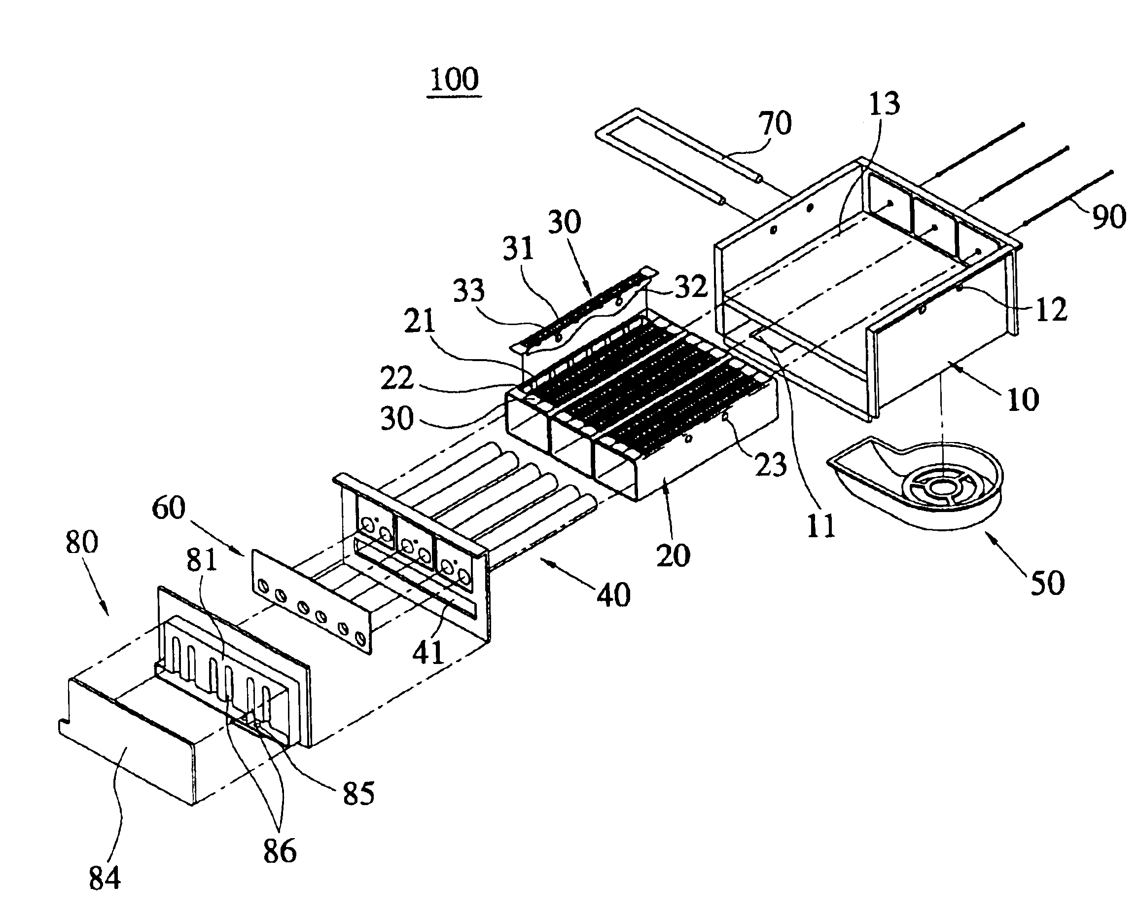
[0048]Referring to FIGS. 3 through 10, a combustion gas burner 100 enabling a multi-stage control includes a number of premixed combustion gas burners. These include at least one tube-shaped burner 20 and at least one plate-shaped burner 30, each having an identical burner output capacity. The burners 20, 30 are disposed in parallel with one another in which a number of operating burners are varied according to a desired calorie.

[0049]Preferably, the combustion gas burner 100 enabling a multi-stage control includes a main casing 10, at least one tube-shaped burner 20, at least one plate-shaped burner 30, a number of mixture supply tubes 40, a Venturi tube 60, and a manifolder 80.

[0050]An air blower 50 is mounted on the bottom surface of the main casing 10 so that air can be supplied from the air ...


PUM


Abstract

A combustion gas burner enabling a multi-stage control including a main casing on the bottom surface of which an air blower is mounted so that air can be supplied from the air blower through an air inlet formed in the lower portion of the main casing, a tube-shaped burner mounted on the main casing in which fire hole units each having a number of fire holes formed at a predetermined distance from one another are disposed on the upper end surface of the main casing in order to burn gas and air which are mixed and supplied to the tube-shaped burner, a plate-shaped burner which is detachably disposed between the fire hole units formed on the upper end surface of the tube-shaped burner, and includes fire hole units having a number of fire holes, a number of mixture supply tubes inserted in the tube-shaped burner and disposed at a predetermined distance so that gas and air are mixed and the mixed gas and air is supplied to the tube-shaped burner and the plate-shaped burner, a Venturi tube installed in front of the mixture supply tubes, mixing gas and air and playing a role of distributing an amount of flow of the mixed gas and air which is needed for independent combustion in each burner, and a manifolder connected to the Venturi tube and the mixture supply tubes, controlling an amount of gas and air. A number of premixed combustion gas burners each having an identical output capacity of the burner, are disposed in parallel with one another and a number of operating burners is varied according to a desired calorie.

Description

BACKGROUND OF THE INVENTION[0001]1. Field of the Invention[0002]The present invention relates to a combustion gas burner enabling a multi-stage control, and more particularly, to a combustion gas burner enabling a multi-stage control in which a number of premixed combustion gas burners each having an identical burner output capacity, are disposed in parallel with one another and a number of operating burners are varied according to a desired calorie or heat capacity.[0003]2. Description of the Related Art[0004]As is well-known, a boiler for heating and supplying hot water for use in a general home is divided into an oil boiler and a gas boiler according to a fuel used. The oil boiler or the gas boiler uses a burner for burning oil or gas which is used in the boiler.[0005]Thus, a general burner obtains heat by burning fuel safely and efficiently. According to the kind of fuel used, the burner is classified as either a gas burner for combustion of gas, an oil burner for combustion of ...

Claims


Application Information

Patent Timeline
Patent Type & Authority Patents(United States)
IPC IPC(8): F23D14/04F23D14/10F23D14/00F23D14/34F23N5/00F23D14/08
CPCF23D14/105F23D14/34
Inventor CHO, SEUNG BEOMSUN, HEE SUKLEE, HYUN JIN
Owner KYUNGDONG NAVIEN
Why Eureka
Try Eureka