Solid state surface catalysis reactor

a solid-state surface catalysis and catalyst technology, applied in the direction of generator/motor, generator/motor, physical/chemical process catalyst, etc., can solve the problems of insufficient process efficiency, energy mismatch, and laser, among the most expensive energy sources availabl

Inactive Publication Date: 2005-07-12
NEOKISMET L L C
View PDF34 Cites 38 Cited by
  • Summary
  • Abstract
  • Description
  • Claims
  • Application Information

AI Technical Summary

Benefits of technology

[0042]In one embodiment, the method and apparatus of the present disclosure in the stimulator-generator mode uses a p-n junction to create hot electrons and inject the hot electrons into thin metal overlayer structures that may include catalyst material. By conveying the hot electrons to adsorbates on the catalyst surface the method stimulates a reaction that can, for example, create an abundance of autocatalyst reactants on the catalyst surface.

Problems solved by technology

The tens of femtosecond lifetime for the process causes a broadband resonance feature and hence permits an energy mismatch between hot electron and the receiving adsorbate energy levels.
A laser, however, is one of the most expensive energy sources available.
However, process efficiency needed to render the approach useful was not adequately addressed.
One of the co-authors of that work suggests that they did not achieve the success they wanted because the surface states associated with the electrolyte cooled the electrons.
They achieved some success, and also suffered severe problems with interactions between hot electrons and electrolyte.
Flooding the surface with liquid electrolyte destroys the effectiveness of hot electrons.
Metal-oxide junction surface states have been an unsolved problem with this approach, where liquids flood the reactive surface.
It is now known that outer layers, away from the catalyst surface, of multiple layers of adsorbates that accumulate on the metal-liquid interface trap hot electrons as “polaritons” and render them less useful as a source of prompt reaction stimulators or as generators of excitations.

Method used


Image

  • Solid state surface catalysis reactor
  • Solid state surface catalysis reactor
  • Solid state surface catalysis reactor

Examples


Embodiment Construction

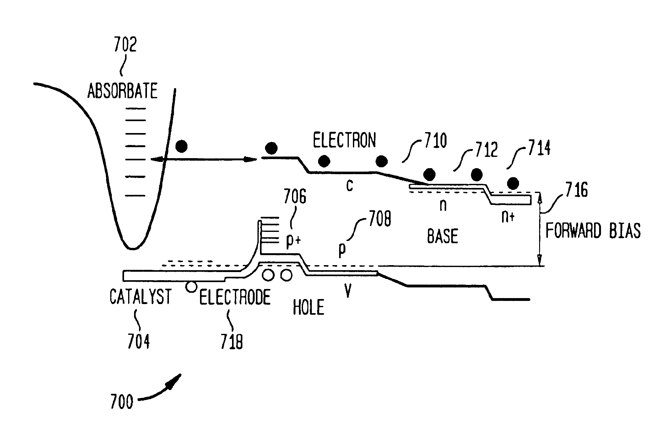
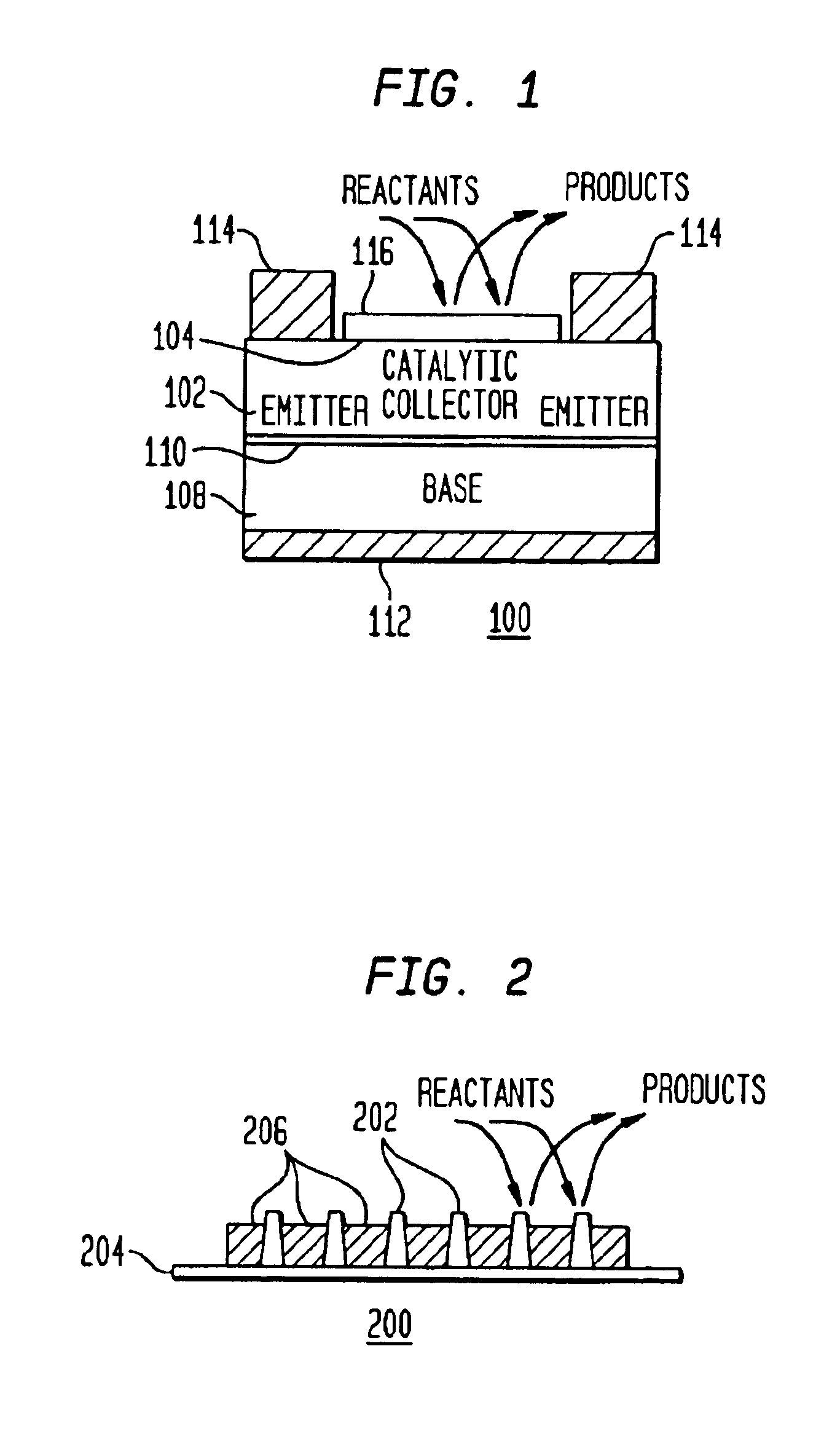
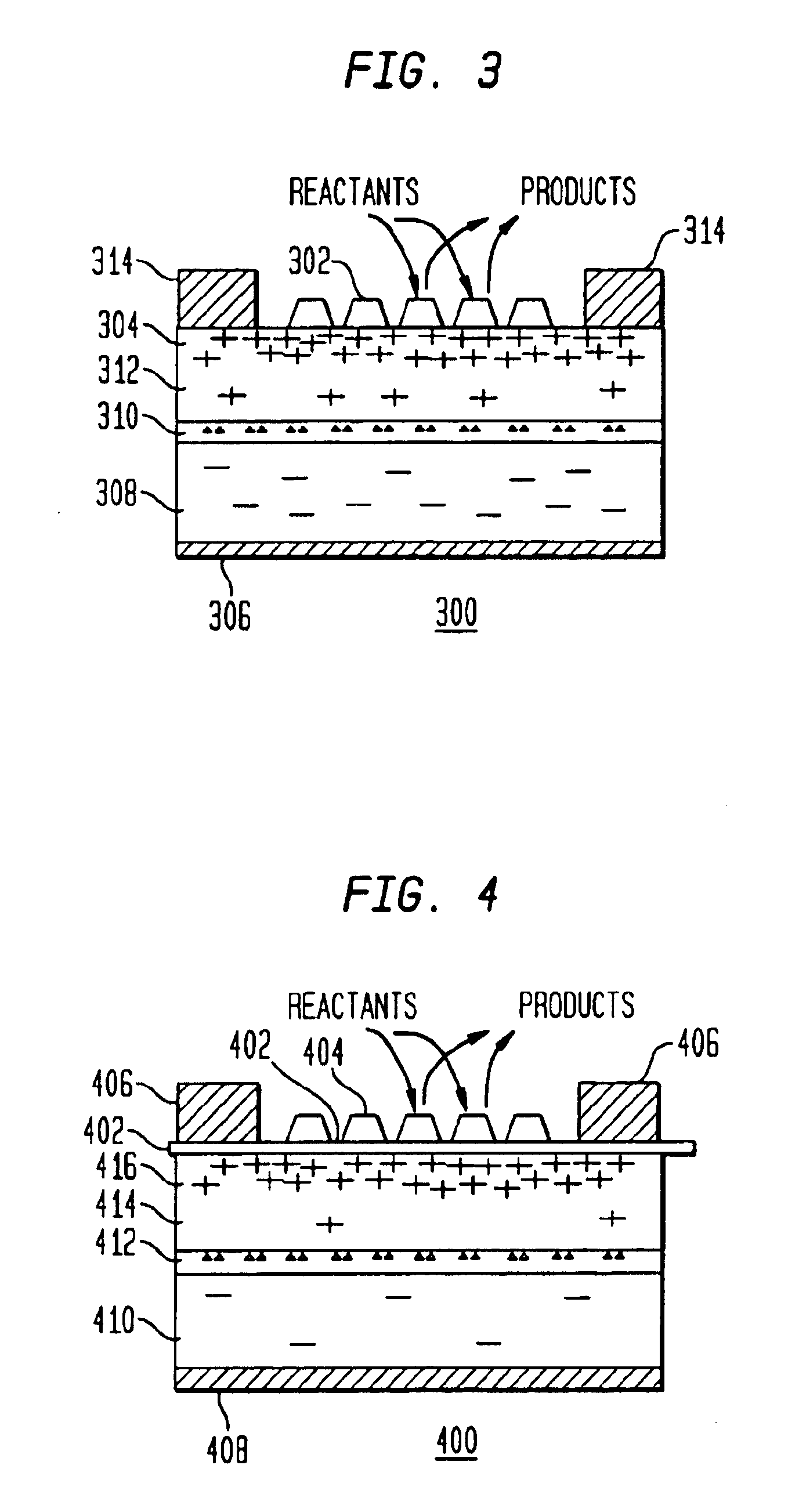
[0055]In one embodiment, the method and apparatus of the present disclosure uses hot electron energy to initiate and or simulate chemical reactions which would otherwise not occur by thermal processes alone. The non-thermal, hot electron energy tailors reaction paths between adsorbates and gas reactants interacting with a catalyst surface. One source of hot electrons is the reaction of fuel and oxidizer on a catalyst structures. Another source uses two terminal electrical devices in contact with the catalyst surface. Electricity can be generated using the same method and device from the pulsed reactions stimulated by hot electron injection. In one embodiment, the method and apparatus couples the excitation structure of a semiconductor substrate to the excitation structure of reactive adsorbates on the surface of a catalyst, The coupling is used, in one embodiment, to stimulate reactions and / or to convert chemical energy into a useful form.

[0056]In one embodiment, the method and appa...


PUM

PropertyMeasurementUnit
partial pressureaaaaaaaaaa
thicknessaaaaaaaaaa
thicknessaaaaaaaaaa

Abstract

A method and apparatus to stimulate chemical reactions on a catalyst surface using electricity, and the reverse process to convert energy released from chemical reactions into electricity. A reversible emitter generates electrons which are injected into reactants on the catalyst surface, exciting chemically reactive vibrational resonances. Hot electrons created in the emitter region of a semiconductor junction diffuse to the co-located collector region and catalyst surface. Catalyst clusters or films bonded on the collector surface transfer the hot electrons to or from the catalyst surface having adsorbed reactants. The dimension of the catalyst-collector is less than the energy mean free path of hot electrons. The hot electrons excite reactant vibrations before thermalizing with the substrate lattice thereby accelerating reactions. The hot electrons are also generated by the same reactions on a catalyst surface. The method and apparatus is reversible and may be operated as an electric generator using chemical reactions.

Description

CROSS-REFERENCE TO RELATED APPLICATIONS[0001]This application is a continuation-in-part of commonly-assigned and U.S. patent application Ser. No.: 09 / 589,669 filed on Jun. 7, 2000, now U.S. Pat. No. 6,327,859 which is a divisional application of U.S. patent application Ser. No. 09 / 304,979 filed on May 4, 1999, now U.S. Pat. No. 6,114,620 and claims the benefit of the U.S. Provisional Patent Application No. 60 / 186,567 filed on Mar. 2, 2000, U.S. Provisional Patent Application No. 60 / 160,531 filed on Oct. 20, 1999, U.S. Provisional Patent Application No.: 60 / 177,919 filed on Jan. 25, 2000.TECHNICAL FIELD OF THE INVENTION[0002]The present invention relates generally to a reaction stimulator and energy converter.BACKGROUND OF THE INVENTION[0003]Recent experimental and theoretical developments in surface science showed how hot electrons cause heating of the vibration of molecules or atoms adsorbed on a catalyst surface. The energy of hot electrons is defined as electrons with effective t...

Claims


Application Information

Patent Timeline
Patent Type & Authority Patents(United States)
IPC IPC(8): B01J35/00H01L29/66H02N6/00H02N11/00H01L41/113
CPCB01J35/002B01J35/0033H02S99/00H02N11/002H01L29/66Y02E10/50
Inventor ZUPPERO, ANTHONY C.GIDWANI, JAWAHAR M.
Owner NEOKISMET L L C
Why Eureka
Try Eureka