Method and apparatus for recording digital images on photosensitive material

Inactive Publication Date: 2005-07-12
BOQART ZAC +1
View PDF19 Cites 8 Cited by
  • Summary
  • Abstract
  • Description
  • Claims
  • Application Information

AI Technical Summary

Benefits of technology

[0010]It is an object of this invention to provide a method and apparatus for precisely delivering light to photosensitive material to allow the printing of extremely high quality continuous tone images from digital information.
[0011]It is a further object of this invention to provide a method and apparatus for blending the pixels of an image presented in digital form, so as to increase the apparent resolution and sharpness of the resulting printed image.
[0012]It is a further object of this invention to provide a low cost imaging head capable of precisely delivering light to photosensitive material with the precision required to allow the printing of extremely high quality continuous tone images.
[0013]In accordance with a preferred embodiment of the invention, the imaging head is comprised of square or rectangular pixel image generators, e.g., fiber optic tubes, mounted to form a rectangular array . The pixel image generators are inclined at an angle of 45 degrees to the scan direction. As the print head scans, each fiber optic tube can expose a pixel image onto the photosensitive material. The exposure levels of the pixel images are preferably specified in a digital file representing an image to be printed. As a result of being inclined at 45 degrees, the pixel images exposed onto the photosensitive material are diamond shaped. Each pixel image overlaps its neighbor by substantially 50% of the center to center distance between pixel images. The pattern resulting from the overlapping of the pixels images generates geometrically interpolated pixel areas with each such area being about 25% of the original pixel image area. Further, the shape of each pixel relative to the scan direction causes the exposure in the area between adjacent scan lines to remain consistent and to cause superior blending of each pixel image with its neighboring pixel images.

Problems solved by technology

Poor alignment, or uneven spacing of the output ends of the fibers cause distortions in the images being generated.
Misalignment of one pixel relative to its neighbors will cause unwanted lines or other artifacts to appear in a continuous tone image.

Method used


Image

  • Method and apparatus for recording digital images on photosensitive material
  • Method and apparatus for recording digital images on photosensitive material
  • Method and apparatus for recording digital images on photosensitive material

Examples


Embodiment Construction

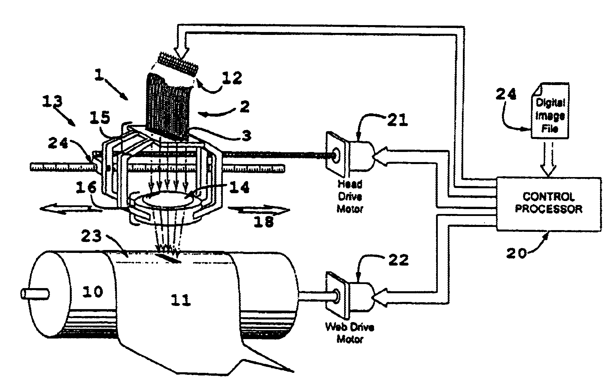
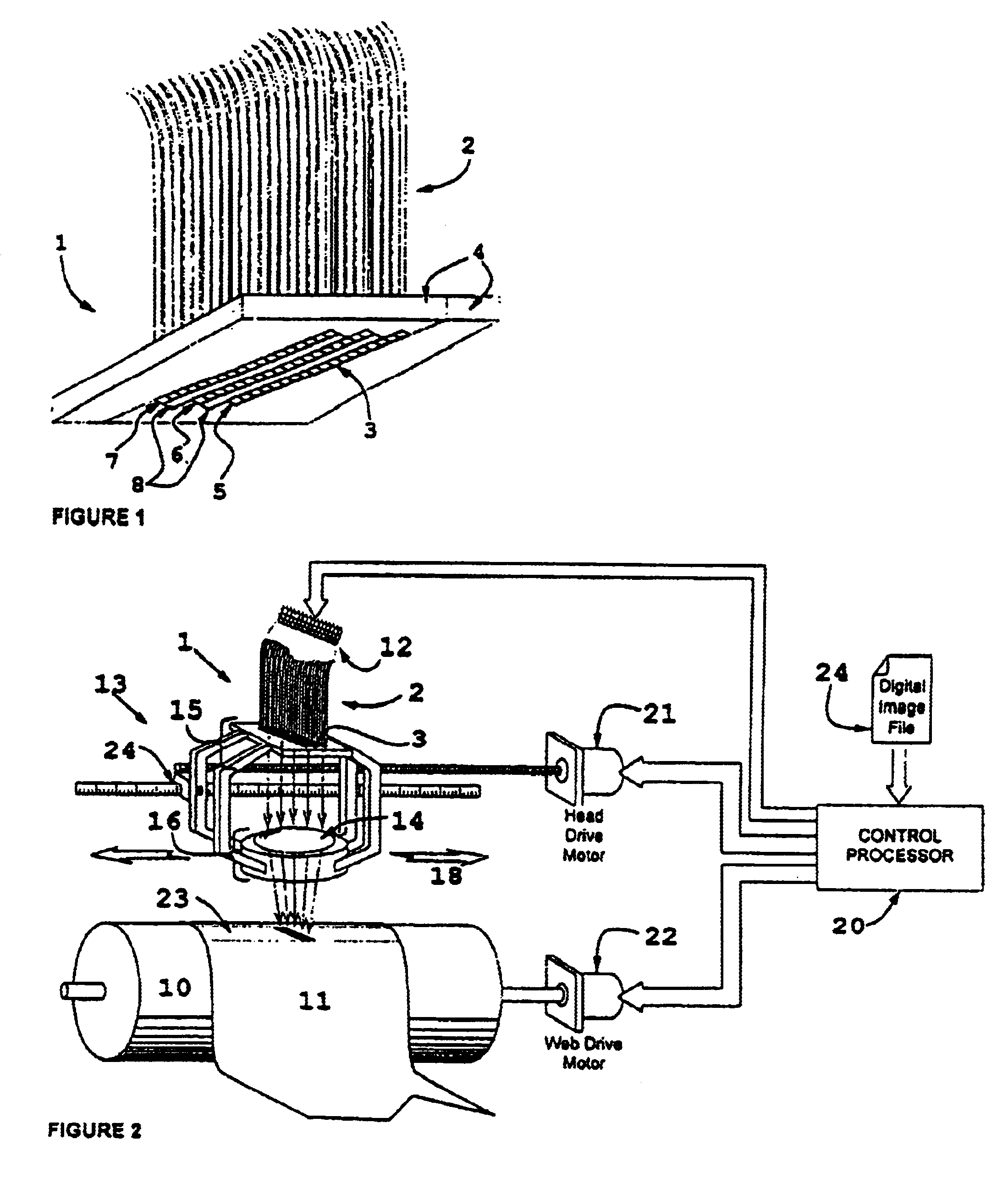
[0027]FIG. 1 shows the output end of an imaging or print head 1 in accordance with a preferred embodiment of the invention. The head is comprised of a plurality of pixel image generators, e.g., light sources defined by fiber optic tubes. The tubes are preferably of substantially square or rectangular cross section and are arranged in columns 5, 6, 7. The fiber optic tubes are selected or manufactured to be of precise cross sectional dimension. With the aid of an assembly fixture, the fiber optic tubes are clamped by frame 4 or bonded in place. Each column is comprised of multiple fiber optic tube output ends which are assembled and positioned in precise alignment with one another. The columns may be arranged in contact, or spaced apart with precision spacers 8. In either configuration, each column contains the same number of fiber optic tubes and is precisely the same length. After assembly, the fiber optic tube ends are machined to a predetermined cross section and polished. Althou...


PUM


Abstract

The present invention is directed to a method and apparatus for exposing photosensitive material to form high quality continuous tone and / or color images thereon. The preferred apparatus includes an imaging head comprised of a plurality of red light sources, a plurality of green light sources, and a plurality of blue light sources. The light produced by said green light sources is passed through a first filter having a narrow spectral transmission characteristic in the green spectral range. Similarly, the light produced by said blue light sources is passed through a second filter having a narrow spectral transmission characteristic in the blue spectral range.

Description

RELATED APPLICATIONS[0001]This application is a continuation of U.S. application Ser. No. 09 / 303,258 filed on Apr. 30, 1999 now abandoned which claims priority based on provisional application 60 / 083,975 filed May 1, 1998.FIELD OF THE INVENTION[0002]This invention relates generally to a method and apparatus for producing high quality continuous tone and / or color images on photosensitive material (i.e., photographic paper or film) from information provided in digital form.DESCRIPTION OF PRIOR ART[0003]In the field of photographic digital printers and image setters, the use of multiple light sources to create individual pixels is well known. U.S. Pat. No. 3,988,742 describes using LEDs and fiber optic light guides to deliver the light to the photosensitive material. Applications of this technology have included type setting, and the generation of lithographic films for printing. In these applications, the light output of LEDs is coupled into the input end of the fiber optic tubes. The...

Claims


Application Information

Patent Timeline
IPC IPC(8): B41J2/45B41J2/46B41J2/447G06K15/02G06K15/10G06K15/12
CPCB41J2/46G06K15/102G06K15/1233B41J2/451B41J2/455G06K2215/0094
Inventor BOQART, ZACBROWNING, JAMES
Owner BOQART ZAC
Why Eureka
Try Eureka