Image processing method, an image processing device and a bonding apparatus

a technology of image processing and bonding apparatus, which is applied in the direction of semiconductor/solid-state device testing/measurement, program control, instruments, etc., can solve the problems of large increase in the amount of calculations required, inability to achieve high-precision position correction, and difficulty for operators to find such alignment points

Inactive Publication Date: 2005-07-12
SHINKAWA CO LTD
View PDF3 Cites 28 Cited by
  • Summary
  • Abstract
  • Description
  • Claims
  • Application Information

AI Technical Summary

Benefits of technology

[0017]Accordingly, the object of the present invention is to provide a means which makes it possible to realize high-precision position detection without performing pattern matching in the direction of rotation (which tends to require a large amount of calculations) even in cases where the object of detection is disposed in an attitude that includes a positional deviation in the direction of rotation.

Problems solved by technology

Such a high-precision position correction cannot be accomplished even if pattern matching detection using a registered reference image is performed.
However, it is difficult for the operator to find such alignment points.
However, such error is a major problem in cases where it is necessary to deal with the finer pitches that have been used in recent years, i.e., finer pitches between the pads P and between the leads L.
As a result, the amount of calculations required greatly increases, thus slowing down the recognition speed.
Thus, such methods are not practical.

Method used


Image

  • Image processing method, an image processing device and a bonding apparatus
  • Image processing method, an image processing device and a bonding apparatus
  • Image processing method, an image processing device and a bonding apparatus

Examples


second embodiment

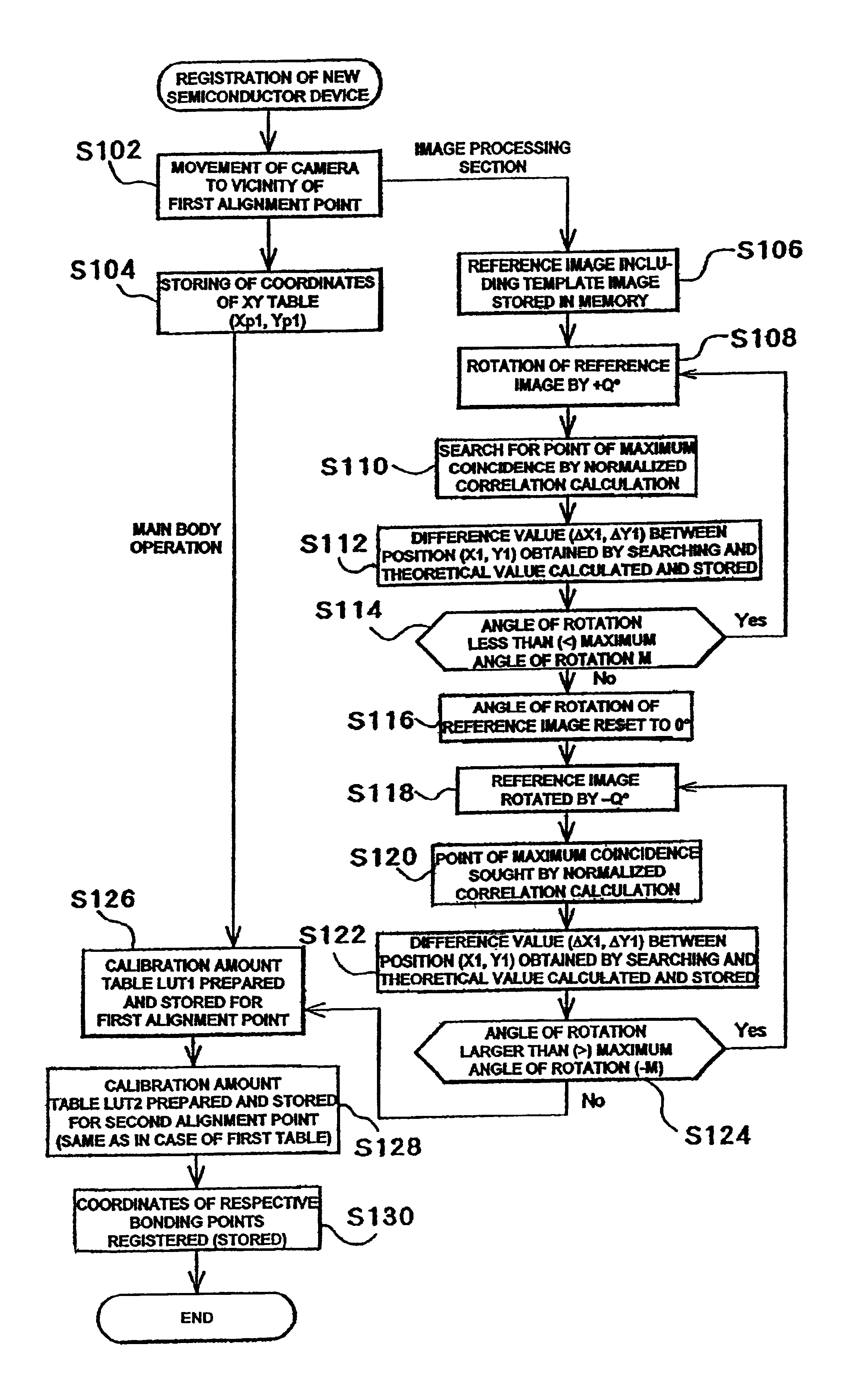
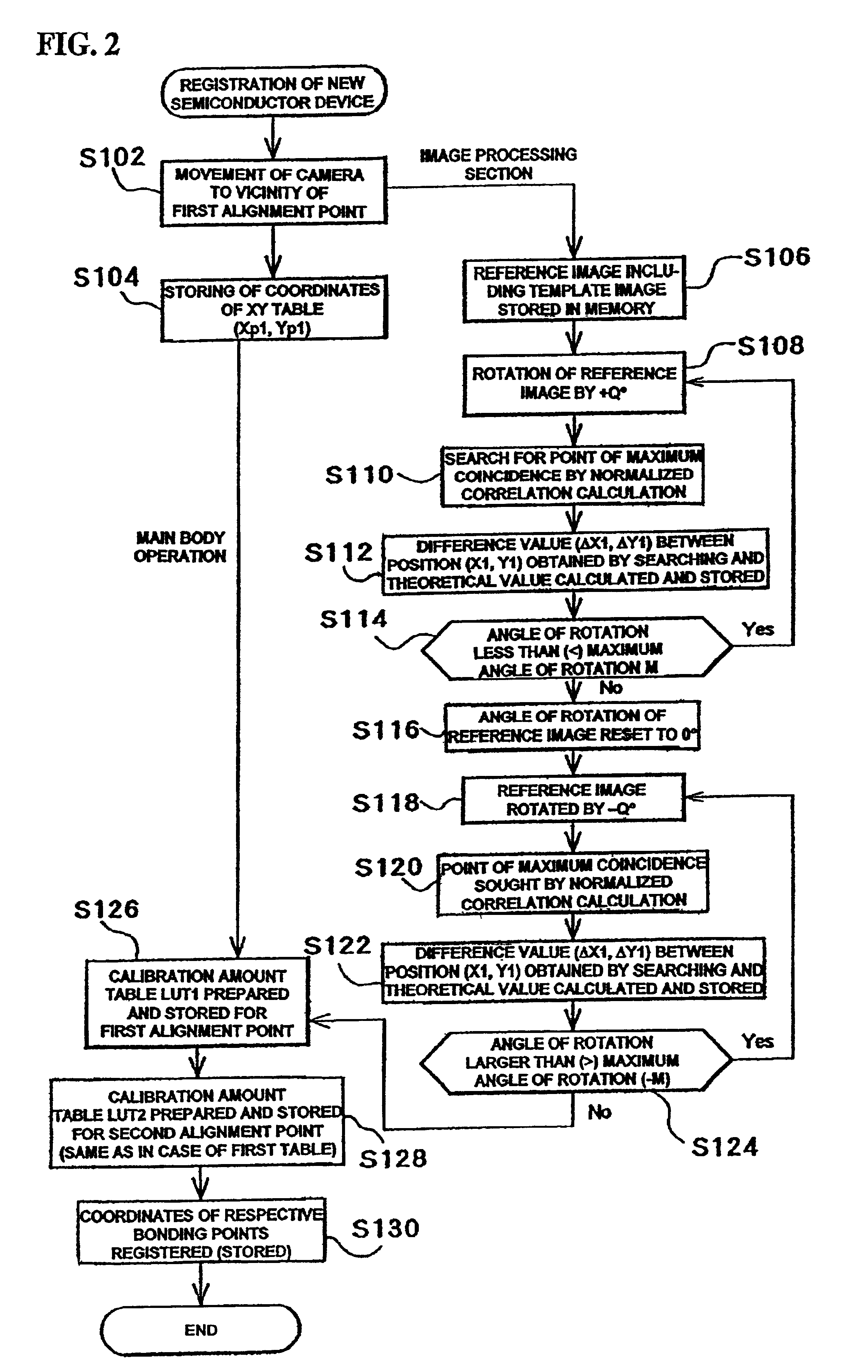
[0093]Next, the second embodiment of the present invention will be described. In the second embodiment, two alignment points are specified for a single object of detection; and in the pattern matching that is performed on the image of the object of detection, such two alignment points are included in a single image frame. The mechanical construction of the second embodiment is substantially the same as that of the first embodiment, and thus a detailed description thereof is omitted.

[0094]In the second embodiment, as seen from FIG. 11, a semiconductor device 14 which has two reference patterns D and E in a region located on the inside with respect to the positions of the pads P on the semiconductor chip 14a is used. In this embodiment, the respective center points Dc and Ec in these reference patterns D and E are used as the first alignment point A1 and second alignment point A2, respectively. In addition, the respective center points of the pads P constitute the bonding points. More...


PUM

PropertyMeasurementUnit
angle of rotationaaaaaaaaaa
anglesaaaaaaaaaa

Abstract

So as to perform high-precision position detection without performing pattern matching in the direction of rotation even when the object of detection involves a positional deviation in the direction of rotation, pattern matching between a reference image and a rotated image obtained by rotating this reference image is performed during registration, and then the difference between the measured value of the position obtained following rotation and the theoretical value of the position of the rotated image is retained as a calibration amount corresponding to the known angle of rotation. Upon detection, the measured value is detected by pattern matching between an image of the object of detection, which is detected by imaging the object of detection disposed in an attitude that includes a positional deviation in the direction of rotation, and a reference image; and this measured value is corrected by the calibration amount.

Description

BACKGROUND OF THE INVENTION[0001]1. Field of the Invention[0002]The present invention relates to an image processing method, an image processing device and a bonding apparatus that includes such an image processing device and more particularly to a method and device that detects the position of an object of detection by way of performing pattern matching of the object of detection and a reference image.[0003]2. Prior Art[0004]In image processing techniques, a pattern matching is widely used. The pattern matching generally uses a portion of a reference image (constituting a known image) as a template image in order to detect the position of an object of detection by detecting the position of this known image contained in the image of the object of detection.[0005]A position detection method that uses such pattern matching will be described with reference to a wire bonding apparatus, which is a semiconductor assembly apparatus, as an example.[0006]In a wire bonding apparatus, wires, t...

Claims


Application Information

Patent Timeline
Patent Type & Authority Patents(United States)
IPC IPC(8): B23K20/00H01L21/68H01L21/67G06T1/00G06T7/00G06T7/60H01L21/60H01L21/66
CPCB23K20/004H01L21/681H01L24/78H01L24/85G05B2219/45033H01L24/45H01L2224/05624H01L2224/45144H01L2224/78301H01L2224/78901H01L2224/85H01L2924/01004H01L2924/01013H01L2924/01015H01L2924/01039H01L2924/01052H01L2924/01074H01L2924/01075H01L2924/01079H01L2924/01082H01L2924/00014H01L2924/01033H01L2224/48624H01L2924/00H01L24/48H01L2224/05554H01L22/00
Inventor SUGAWARA, KENJI
Owner SHINKAWA CO LTD
Why Eureka
Try Eureka