
RF multiple load cell scale

a load cell and scale technology, applied in the field of weighing apparatus, can solve the problems of scale often requiring recompensation for load position, inability to monitor individually, uneven wear on the load cell,

Inactive Publication Date: 2005-07-19
METTLER TOLEDO INC
View PDF14 Cites 47 Cited by
  • Summary
  • Abstract
  • Description
  • Claims
  • Application Information

AI Technical Summary

Benefits of technology

This solution enhances accuracy, reduces maintenance costs, and improves reliability by allowing for remote monitoring and compensation of load cells, while eliminating cable-related failures and power interruptions.

Problems solved by technology

Since the load cell cannot rotate, the wear on the load cell is not distributed evenly.
When the analog circuits of the load cells are connected together, they are essentially impossible to monitor individually.
Thus, “trouble shooting” or repair of a scale, can require disassembly of the electrical circuits in order to test the load cells individually and find the defective one.
Further, when a load cell is replaced for any reason, the scale often requires recompensation for load position.
For large scales in particular this is a time consuming procedure, and the known weight is often inconvenient to obtain.
The cables are expensive and subject to being damaged, being pinched, being eaten by rodents, and failing.
The cables tend to break down due to weather changes.
This requires the scale to be repaired at heavy cost.
This also means that the scale can be down for long periods of time.
There is a large risk to the scale due to lightening damage because of the wiring in the scale.
There is also risk of power interruption to the large capacity scale, which would shut down the ability to use the scale.
There is also a limitation on the control house based on the need to run cables from the control house to the scale.

Method used


Image

  • RF multiple load cell scale
  • RF multiple load cell scale
  • RF multiple load cell scale

Examples


Embodiment Construction

[0043]The preferred embodiment of the invention is a weighing platform connected to a control house via a wireless RF connection. The preferred embodiment is a multiple load cell configuration.

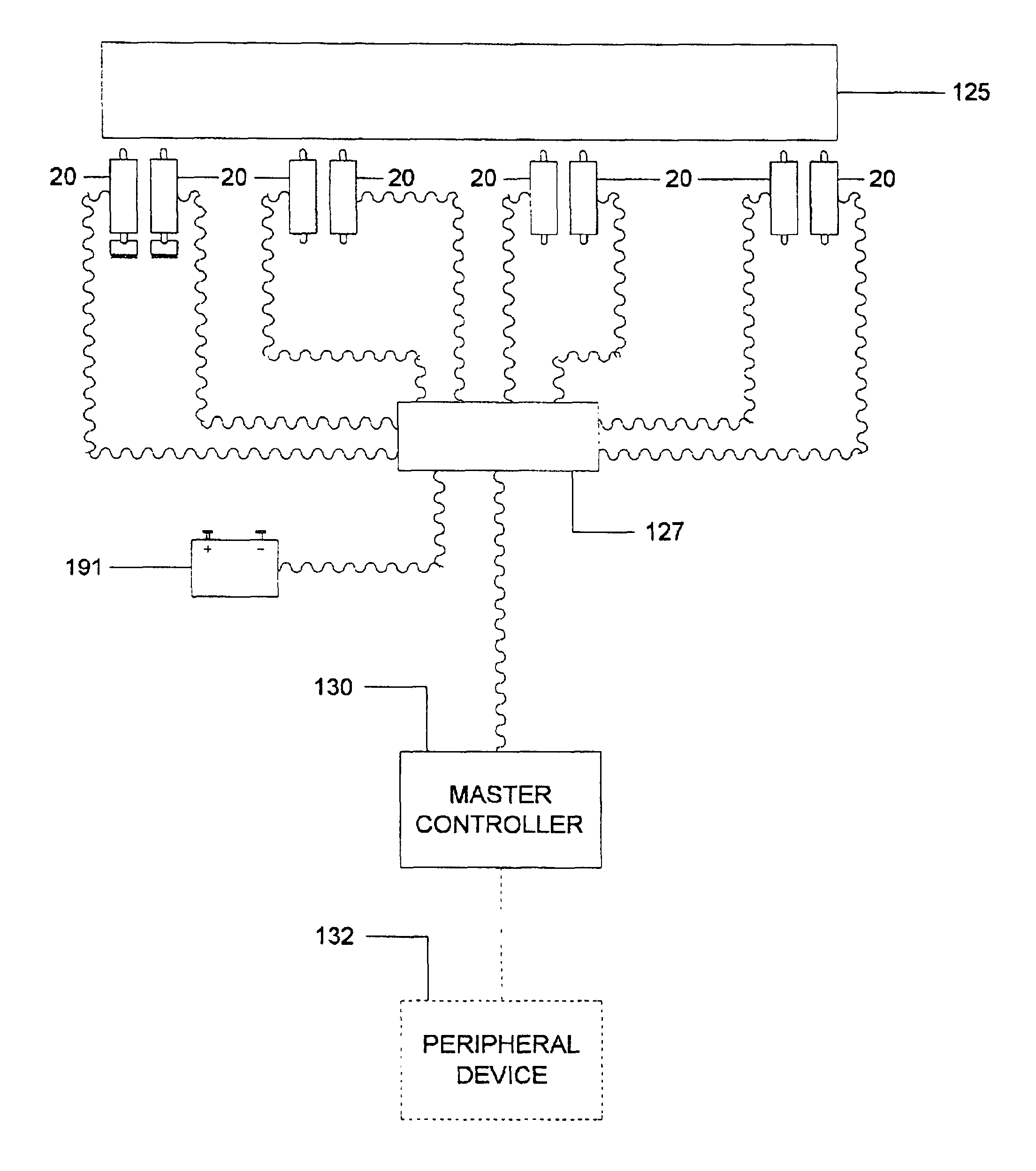
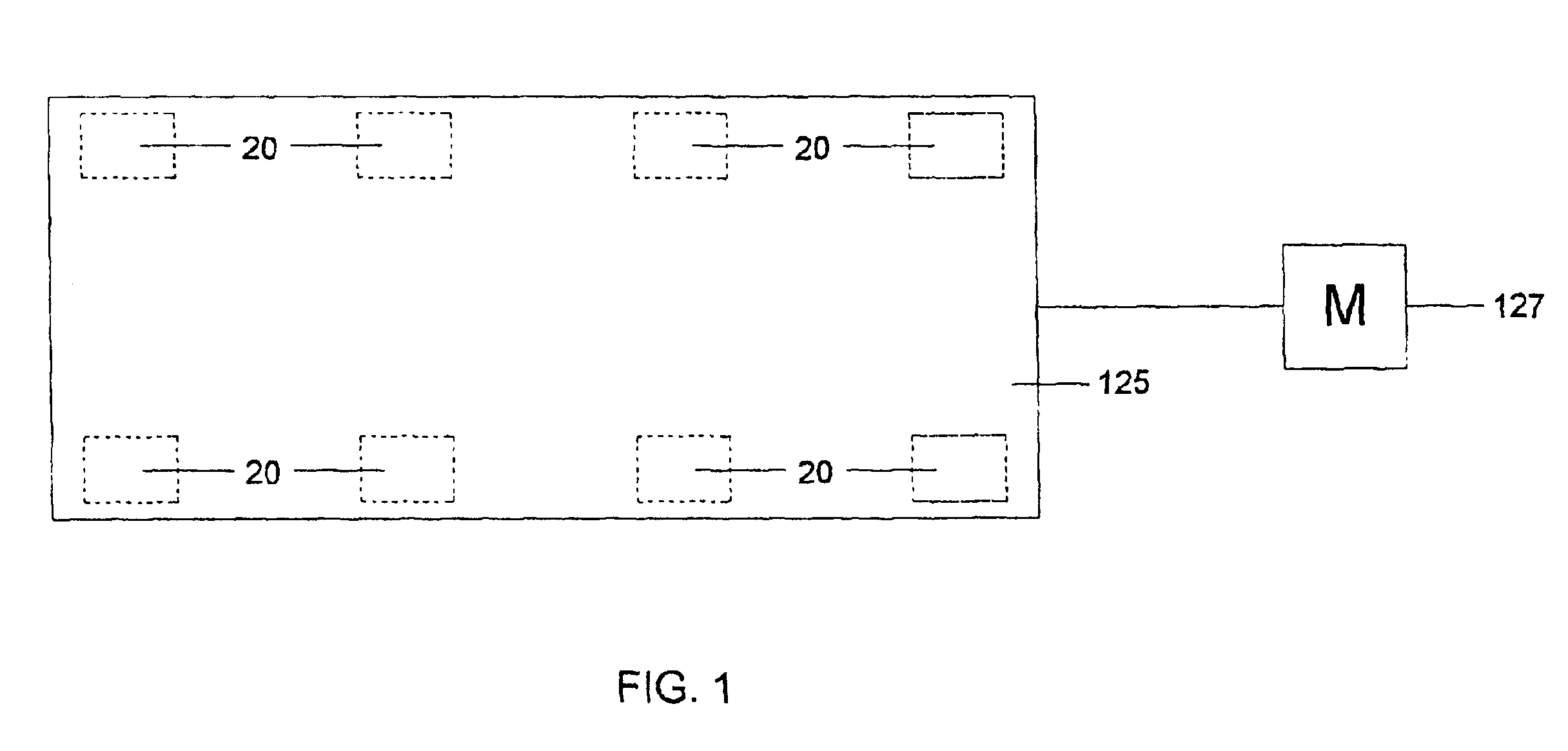
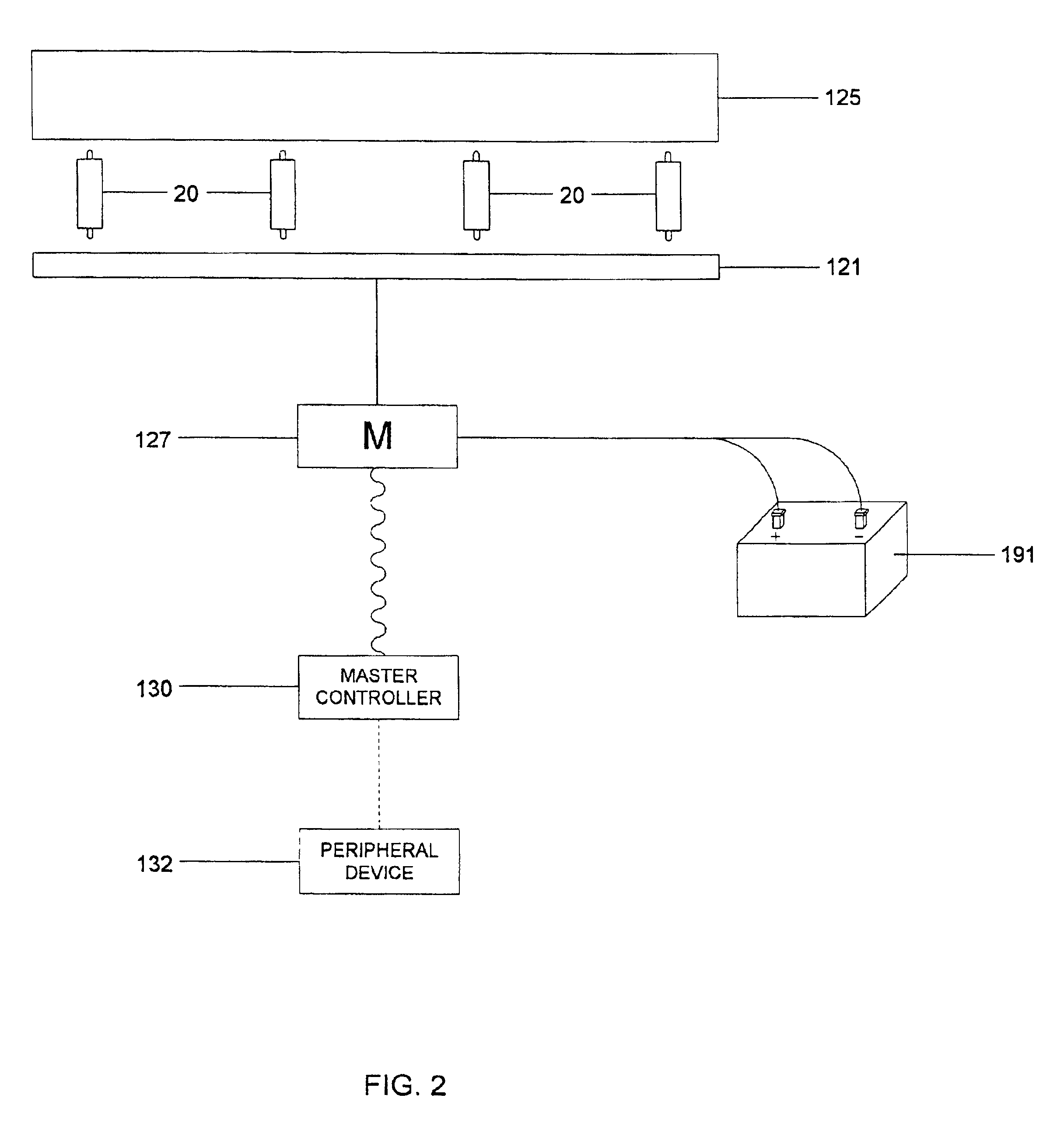
[0044]Referring to FIGS. 1 and 2, there is shown a configured as a single scale for weighing vehicles. The system includes eight digital load cells 20 on the scale deck structure 121 supporting a platform 125 suitable for holding a vehicle such as a truck. The load cells 20 are connected together through a junction box 127 and through RF transmission to a master controller 130. The master controller may be connected to one or more peripheral devices 132 such as a printer or host computer. The digital load cells 20, junction box / concentrator 127 and master controller 130 are arranged and programmed with junction box / concentrator 127 performing as the master and the load cells 20 as slaves The junction box / concentrator 127 transmits to the master controller 130. The junction box / concentrator 127...


PUM


Abstract

Load cells forming one or more weighing scales are connected to each other and to a common concentrator which communicates to a master controller in the control house via RF wireless communication. The load cells are polled by and provide weight reading to concentrator to the master controller. A digital load cell is used which includes a rocker pin, guided beam, torsion ring or other counterforce, a circuit board mounted on the counterforce and an enclosure sealing the circuit board and all but the load bearing surfaces of the counterforce and a mounded antenna. The circuit board includes a microcomputer and a transceiver. RF communication is provided with the circuit board through a antenna mounted on the enclosure. One or a number of load cells may be connected to a computer or controller to form one or more weighing scales with one or more weighing scales connect to a control house through wireless RF communication. The preferred embodiment uses passive receivers for receiving the signals and waveguide to minimize power requirements.

Description

CROSS-REFERENCES TO RELATED APPLICATIONS (IF ANY)[0001]NoneSTATEMENT AS TO RIGHTS TO INVENTIONS MADE UNDER FEDERALLY-SPONSORED RESEARCH AND DEVELOPMENT (IF ANY)[0002]NoneBACKGROUND[0003]1. Field of the Invention[0004]This invention relates to weighing apparatus and, more particularly, to weighing apparatus utilizing multiple load cells and RF (radio frequency) to communicate,[0005]2. Description of Prior Art[0006]Many weighing applications require the use of multiple load cells in a single scale or in a number of associated scales. For example, a heavy capacity scale for weighing trucks or railroad cars requires multiple load cells. Each load cell provides an analog signal proportional to the portion of the load borne by that load cell. Strain gages connected in a wheatstone bridge configuration often provide the analog signal. In heavy capacity applications, the load is distributed over usually at least four load cells and some applications may require sixteen or more load cells. T...

Claims


Application Information

Patent Timeline
Patent Type & Authority Patents(United States)
IPC IPC(8): G01G21/23G01G3/14G01G21/00G01G3/00
CPCG01G3/1408G01G21/23G01G23/3728Y02B60/50
Inventor FRYE, CRAIGHUITT, BRUCE ELDRIDGE
Owner METTLER TOLEDO INC
Learn More