Method and apparatus for automated image analysis of biological specimens

an image analysis and biological specimen technology, applied in the field of medical diagnostics, can solve the problems of continuous need for operator input, inability to accurately inability to include cells of interest errors, etc., to achieve rapid and accurate scan large amounts of biological material, high degree of training, and high cost

Inactive Publication Date: 2005-07-19
CARL ZEISS MICROSCOPY GMBH
View PDF137 Cites 87 Cited by
  • Summary
  • Abstract
  • Description
  • Claims
  • Application Information

AI Technical Summary

Benefits of technology

[0005]A problem with the foregoing automated system is the continued need for operator input to initially locate cell objects for analysis. Such continued dependence on manual input can lead to errors including cells of interest being missed. Such errors can be critical especially in assays for so-called rare events, e.g., finding one tumor cell in a cell population of one million normal cells. Additionally, manual methods can be extremely time consuming and can require a high degree of training to properly identify and/or quantify cells. This is not only true for tumor cell detection, but also for other applic

Problems solved by technology

A problem with the foregoing automated system is the continued need for operator input to initially locate cell objects for analysis.
Such continued dependence on manual input can lead to errors including cells of interest being missed.
Additionally, manual methods can be

Method used


Image

  • Method and apparatus for automated image analysis of biological specimens
  • Method and apparatus for automated image analysis of biological specimens
  • Method and apparatus for automated image analysis of biological specimens

Examples


Embodiment Construction

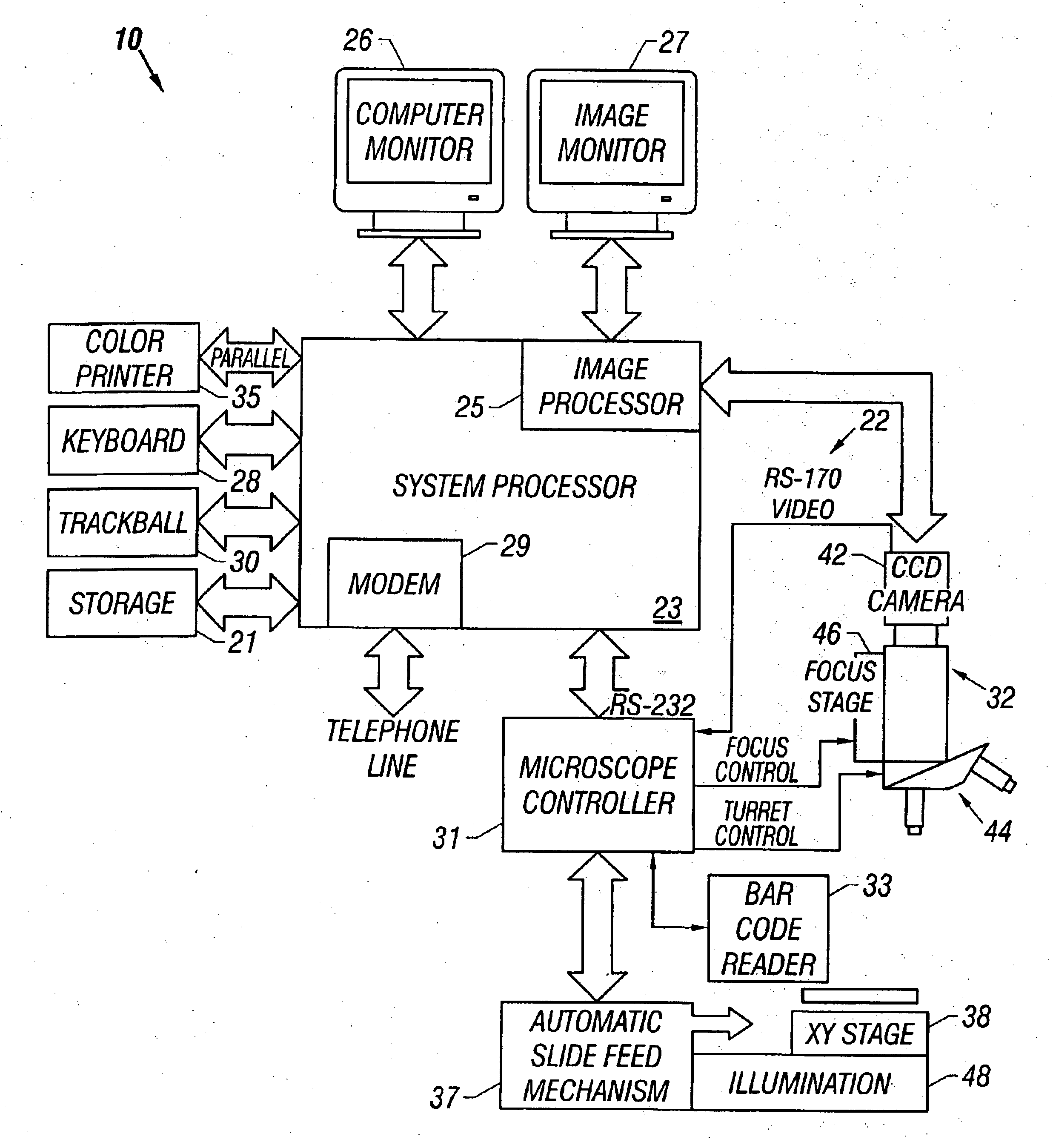
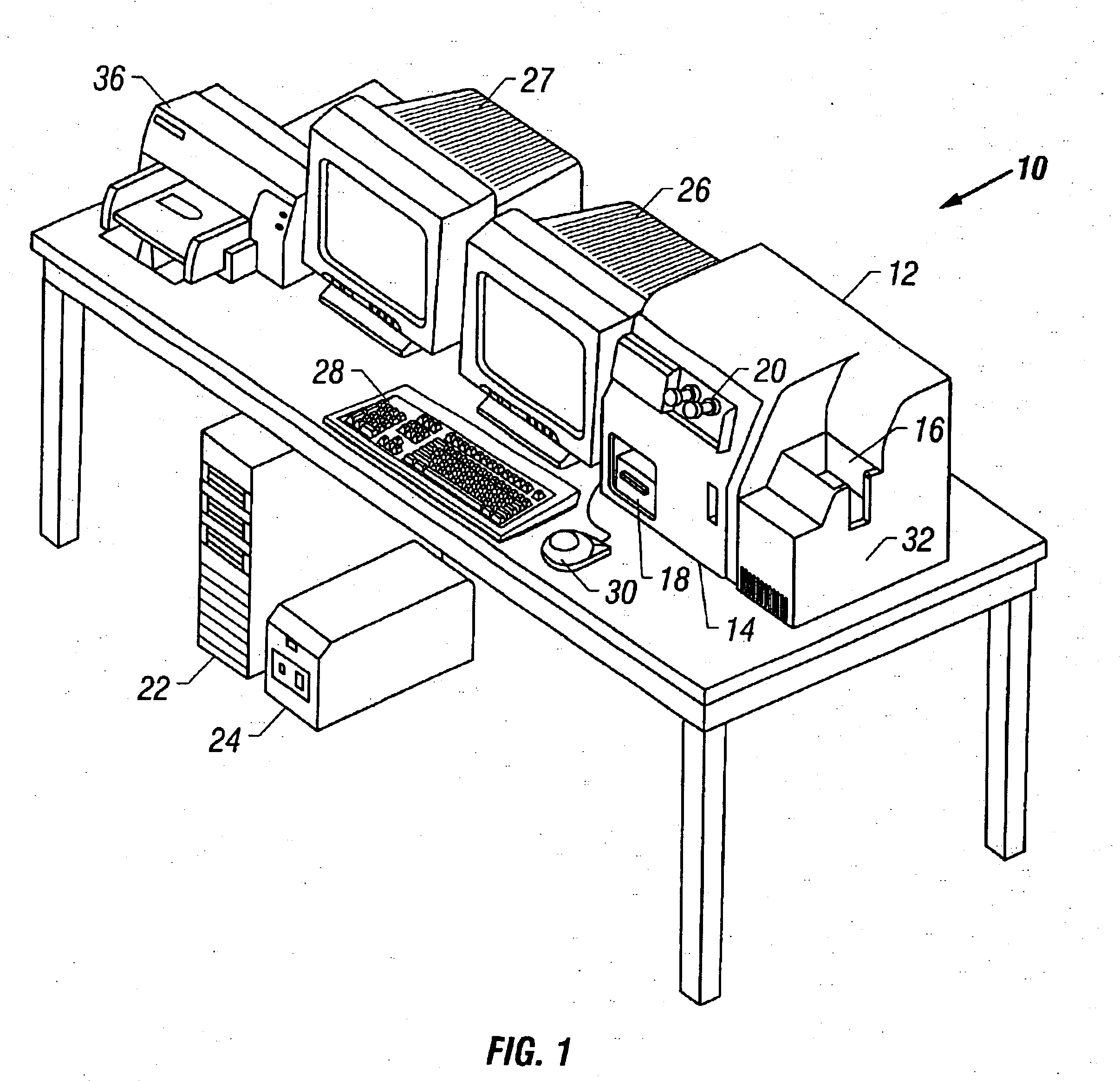
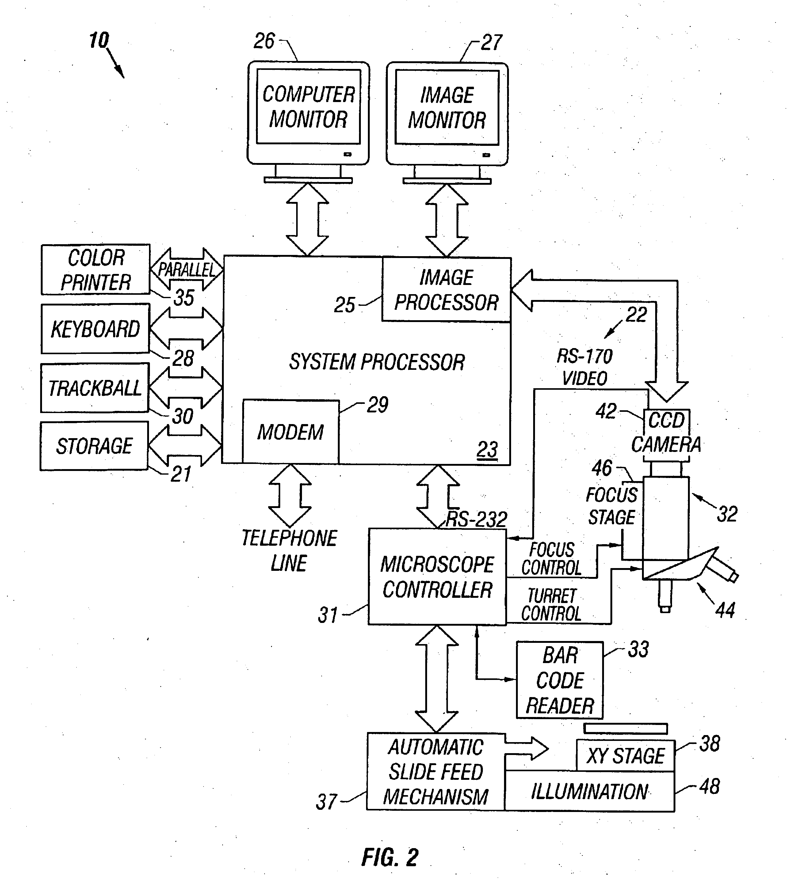
[0045]Referring now to the figures, an apparatus for automated cell analysis of biological specimens is generally indicated by reference numeral 10 as shown in perspective view in FIG. 1 and in block diagram form in FIG. 2. The apparatus 10 comprises a microscope subsystem 32 housed in a housing 12. The housing 12 includes a slide carrier input hopper 16 and a slide carrier output hopper 18. A door 14 in the housing 12 secures the microscope subsystem from the external environment. A computer subsystem comprises a computer 22 having a system processor 23, an image processor 25 and a communications modem 29. The computer subsystem further includes a computer monitor 26 and an image monitor 27 and other external peripherals including storage device 21, track ball device 30, keyboard 28 and color printer 35. An external power supply 24 is also shown for powering the system. Viewing oculars 20 of the microscope subsystem project from the housing 12 for operator viewing. The apparatus 10...


PUM


Abstract

A method and apparatus for automated cell analysis of biological specimens automatically scans at a low magnification to acquire images which are analyzed to determine candidate cell objects of interest. The low magnification images are converted from a first color space to a second color space. The color space converted image is then low pass filtered and compared to a threshold to remove artifacts and background objects from the candidate object of interest pixels of the color converted image. The candidate object of interest pixels are morphologically processed to group candidate object of interest pixels together into groups which are compared to blob parameters to identify candidate objects of interest which correspond to cells or other structures relevant to medical diagnosis of the biological specimen. The location coordinates of the objects of interest are stored and additional images of the candidate cell objects are acquired at high magnification. The high magnification images are analyzed in the same manner as the low magnification images to confirm the candidate objects of interest which are objects of interest. A high magnification image of each confirmed object of interest is stored for later review and evaluation by a pathologist.

Description

[0001]This application is a continuation of U.S. patent application Ser. No. 09 / 492,101, filed Feb. 14, 2000, now U.S. Pat. No. 6,553,135 which is a continuation of U.S. patent application Ser. No. 08 / 758,436, filed Nov. 27, 1996, now U.S. Pat. No. 6,215,892, which claims the benefit of U.S. Provisional Application No. 60 / 026,805, filed Nov. 30, 1995.BACKGROUND OF THE INVENTION[0002]In the field of medical diagnostics including oncology, the detection, identification, quantitation and characterization of cells of interest, such as cancer cells, through testing of biological specimens is an important aspect of diagnosis. Typically, a biological specimen such as bone marrow, lymph nodes, peripheral blood, cerebrospinal fluid, urine, effusions, fine needle aspirates, peripheral blood scrapings or other materials are prepared by staining the specimen to identify cells of interest. One method of cell specimen preparation is to react a specimen with a specific probe which can be a monoclo...

Claims


Application Information

Patent Timeline
IPC IPC(8): G01N15/14G02B21/24G06K9/00G01N1/31G01N33/48G06T1/00G06T7/60
CPCG01N1/312G01N15/1468G01N15/1475G02B21/244G02B21/367G06K9/00127G06K9/00134G06T7/60G01N2015/1472G01N2015/1488G01N2015/1497G06V20/693G06V20/69
Inventor DOUGLASS, JAMES W.RIDING, THOMAS J.RING, JAMES E.
Owner CARL ZEISS MICROSCOPY GMBH
Why Eureka
Try Eureka