Parallel data communication having multiple sync codes

a data communication and parallel technology, applied in the field of data communication, can solve the problems of line impedance and length, anticipated amount of time skew, and sensitive to practicable limitations in terms of implementation space and available operating power

Inactive Publication Date: 2005-07-19
FUTURE LINK SYST
View PDF4 Cites 67 Cited by
  • Summary
  • Abstract
  • Description
  • Claims
  • Application Information

AI Technical Summary

Problems solved by technology

Regardless of the configuration, the communication typically requires closely-controlled interfaces that are designed to ensure that data integrity is maintained while using circuit designs are sensitive to practicable limitations in terms of implementation space and available operating power.
There is often an anticipated amount of time “skew” between the transmitted data signals themselves and between the data signals and the receive clock at the destination.
There are many sources of skew including, for example, transmission delays introduced by the capacitive and inductive loading of the signal lines of the parallel interconnect, variations in the I / O (input / output) driver source, intersymbol interference and variations in the transmission lines' impedance and length.
The shared current sources induce skew at the driver, which directly reduces margin at the receiver, which in turn can cause data transmission errors.
Typically, the greater the number of data bits (or parallel-bus data lines), the more difficult it is to prevent unacceptable levels of skew across all the bits.
With increasing transmission rates, this difficulty is a bottleneck to the number of useful parallel-bus data lines.
For many applications, controlling the skew problem in this manner is unduly tedious and / or costly.
The burdens associated with this approach are significantly increased where the application multiple

Method used


Image

  • Parallel data communication having multiple sync codes
  • Parallel data communication having multiple sync codes
  • Parallel data communication having multiple sync codes

Examples


Embodiment Construction

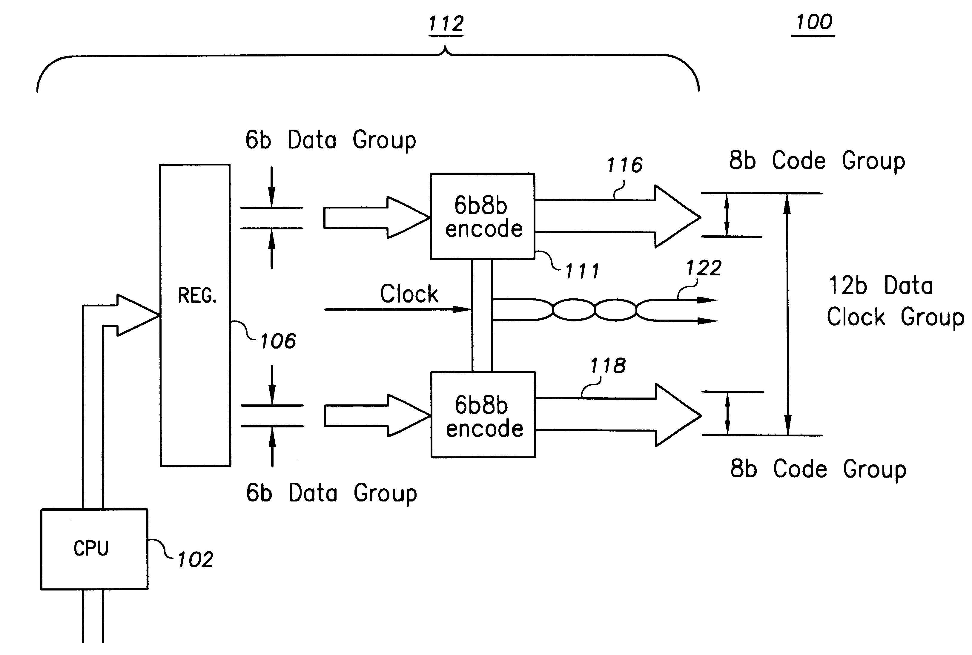
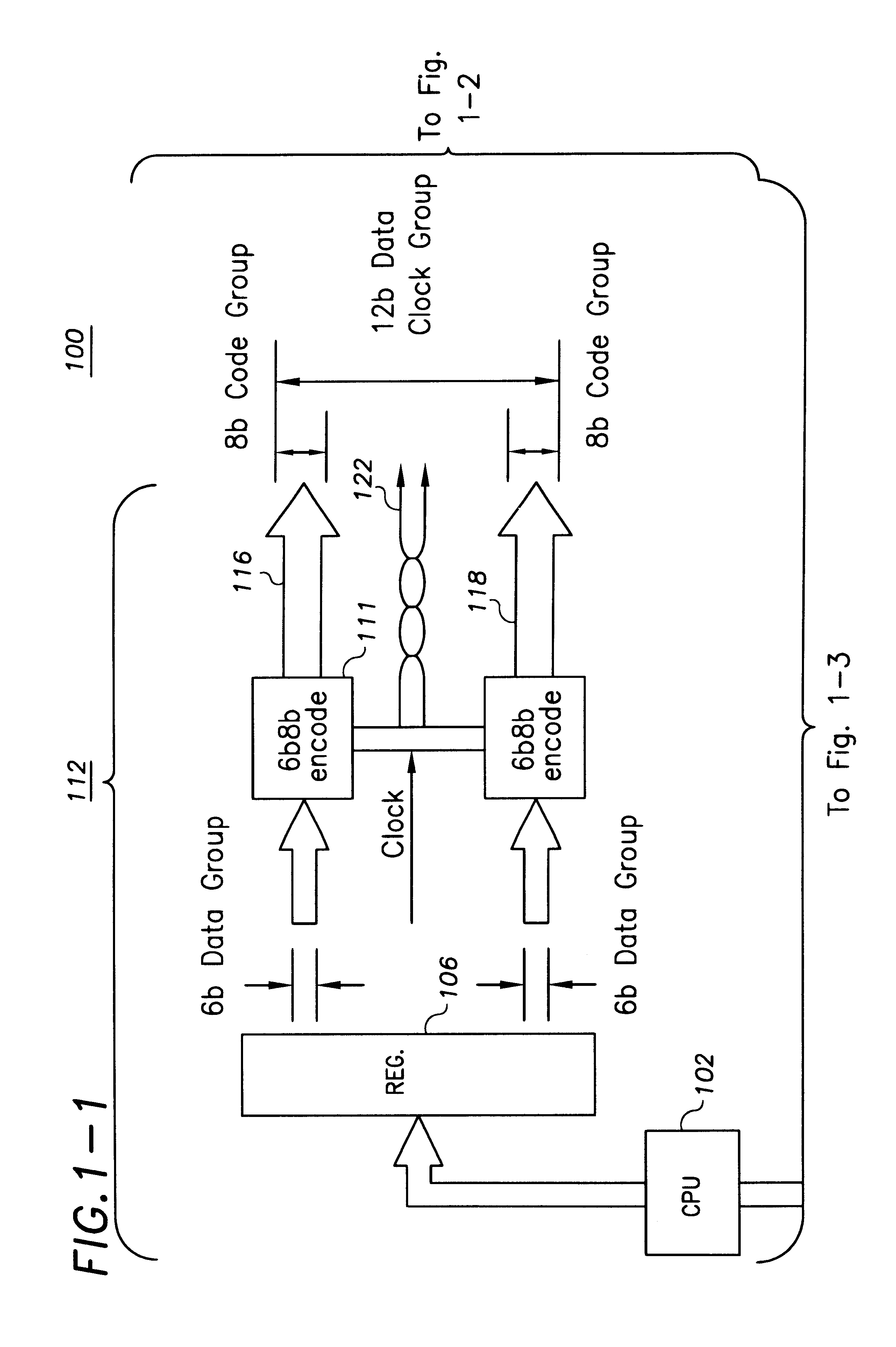
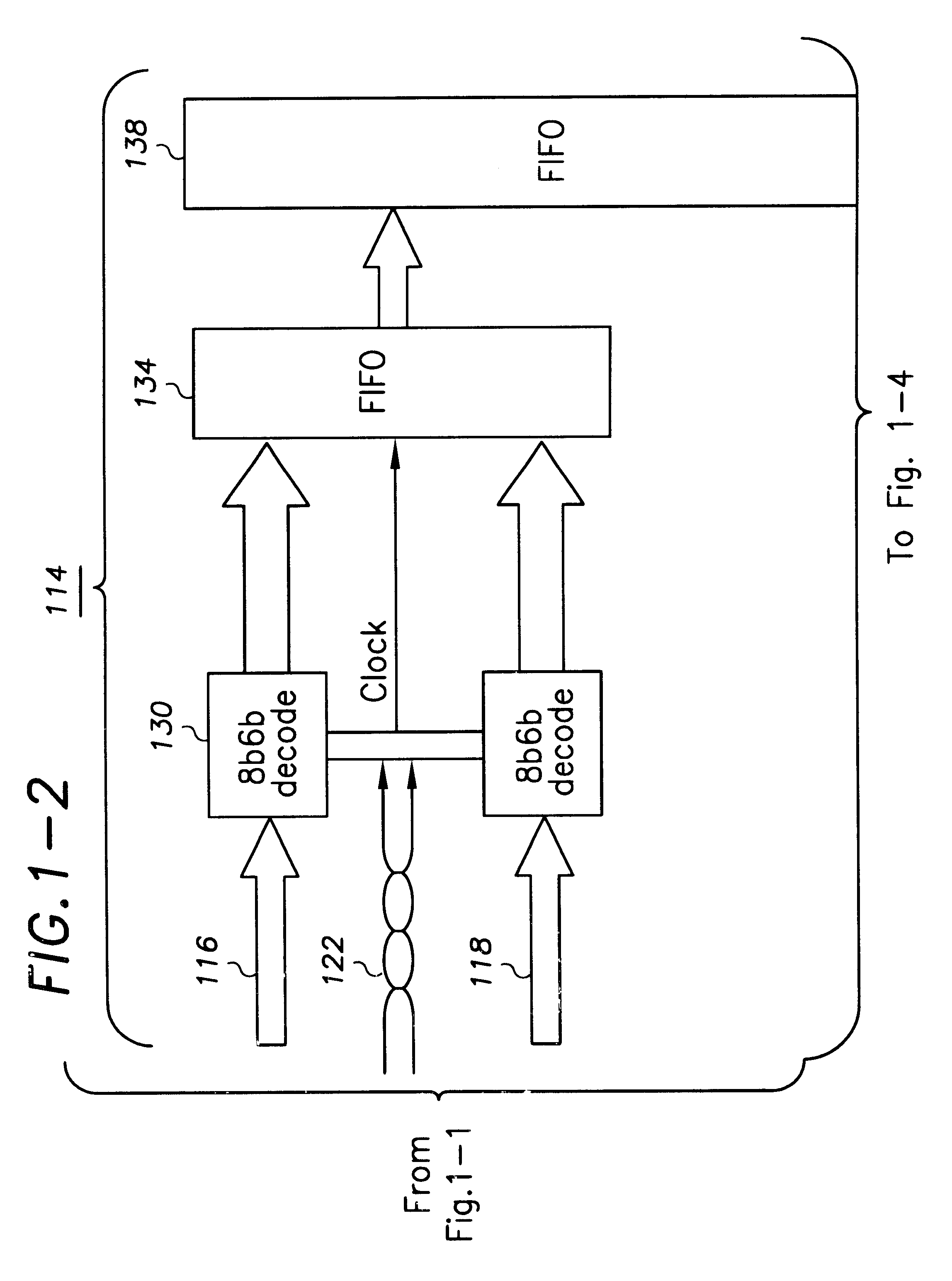
[0020]The present invention is believed to be generally applicable to methods and arrangements for transferring data between two modules (functional blocks) intercoupled by a parallel data communication path. The invention has been found to be particularly advantageous for high-speed data transfer applications susceptible to data-skew errors. Examples of such application include, among others, SSTLS (stub series transceiver / terminated logic), RSL (Ranabus Signaling Logic) interfaces, closely-connected applications such as where the parallel data communication path communicatively couples the two modules on a single-chip, off-board high-speed communication between chips typically situated immediately adjacent each other on the same printed circuit board such as on a reference-chip development platform of the type disclosed in U.S. patent application Ser. No. 09 / 215,942, filed on Dec. 18, 1998, now U.S. Pat. No. 6,347,395. While the present invention is not necessarily limited to such...


PUM


Abstract

A high-speed parallel-data communication approach overcomes skewing problems by transferring digital data with automatic realignment. In one example embodiment, a parallel bus has parallel bus lines adapted to transfer digital data from a data file, along with a synchronizing clock signal. To calibrate the synchronization, the sending module transfers synchronization codes which are sampled and validated according to an edge of the clock signal by a receiving module and then used to time-adjust the edge of the clock signal relative to the synchronization codes. The synchronization codes are implemented to toggle the bus lines with each of the synchronization codes transferred.

Description

RELATED PATENT DOCUMENTS[0001]The present invention is related to and fully incorporates the subject matter disclosed in concurrently-filed U.S. patent application, Ser. No. 09 / 871,197, entitled “Parrallel Communication Based on Balanced Data-Bit Encoding” (now U.S. Pat. No. 6,636,166), Ser. No. 09 / 871,160 entitled “Parallel Data Communication Consuming Low Power,” and Ser. No. 09 / 871,159, entitled “Parallel Data communication Having Skew Intolerant Data Groups.”FIELD OF THE INVENTION[0002]The present invention is directed generally to data communication. More particularly, the present invention relates to methods and arrangements for synchronizing data passed on a parallel data bus that is susceptible to skew-caused errors.BACKGROUND OF THE INVENTION[0003]The electronics industry continues to strive for high-performance, high-functioning circuits. Significant achievements in this regard have been realized through the development of very large-scale integrated circuits. These comple...

Claims


Application Information

Patent Timeline
Patent Type & Authority Patents(United States)
IPC IPC(8): H04L7/00H04L25/14H04L25/49H04L7/04H04L25/02
CPCH04L7/0008H04L25/14H04L25/4908H04L7/04G06F13/42
Inventor EHMANN, GREGORY E.
Owner FUTURE LINK SYST
Why Eureka
Try Eureka