Vibratory transducer

a transducer and vibration technology, applied in the direction of direct mass flowmeters, liquid/fluent solid measurement, using electrical/magnetic means, etc., can solve the problems of increasing the manufacturing cost of such a coriolis mass flowmeter-densimeter, increasing the complexity of the measuring and control circuit, and increasing the mechanical complexity. , to achieve the effect of low total mass of the tube and high sensitivity to primary measurements

Inactive Publication Date: 2005-07-26
ENDRESS HAUSER FLOWTEC AG
View PDF8 Cites 185 Cited by
  • Summary
  • Abstract
  • Description
  • Claims
  • Application Information

AI Technical Summary

Benefits of technology

[0022]Starting from the above prior art, the invention therefore has for its object to provide a vibratory transducer suitable for use in a Coriolis mass flowmeter, particularly in a Coriolis mass flowmeter-densimeter, whose single flow tube or whose flow tubes are easy to manufacture and particularly easy to bend, and whose cross sensitivity to the internal pressure existing in its lumen, or to variations thereof, can be kept at a low level with comparatively simple and particularly low-cost means.
[0028]A fundamental idea of the invention is to keep the flow tube partially as dimensionally stable as possible in the particularly pressure-sensitive area of the at least one arcuate tube segment, at least in the cross section, through low-mass, local stiffening means, thus stabilizing practically the entire flow tube in such a manner that the deformations of the tube lumen caused by the flexural vibrations are nearly independent of the existing internal pressure or independent of the above-mentioned pressure difference. Since relatively small masses are added to the flow tube, whereby the total mass of the tube is kept low, the high sensitivity to the primary measurands, mass flow rate and density, which is achieved with conventional transducers is virtually preserved.

Problems solved by technology

Unfortunately, such cross sensitivities of the transducer to pressure may result in, mostly undesired, cross talks from pressure to mass flow corresponding Coriolis forces.
As is readily apparent, this involves an additional amount of mechanical complexity as well as a considerable additional amount of complexity of the measuring and control circuit, in which additional arithmetic capability must be provided.
On the one hand, this substantially increases the manufacturing costs of such a Coriolis mass flowmeter-densimeter.
On the other hand, such an increase in the complexity of both the installed hardware and the firmware implemented therein entails a disproportionate increase in error probability or even in the probability of failure and, thus, a substantial increase in the complexity of the monitoring necessary to ensure the required reliability of the Coriolis mass flowmeter-densimeter.

Method used


Image

  • Vibratory transducer
  • Vibratory transducer
  • Vibratory transducer

Examples


Embodiment Construction

[0034]While the invention is susceptible to various modifications and alternative forms, exemplary embodiments thereof have been shown by way of example in the drawings and will herein be described in detail. It should be understood, however, that there is no intent to limit the invention to the the particular forms diclosed, but on the contrary, the intention is to cover all modifications, equivalents, and alternatives falling within the spirit and scope of the invention as defined by the intended claims.

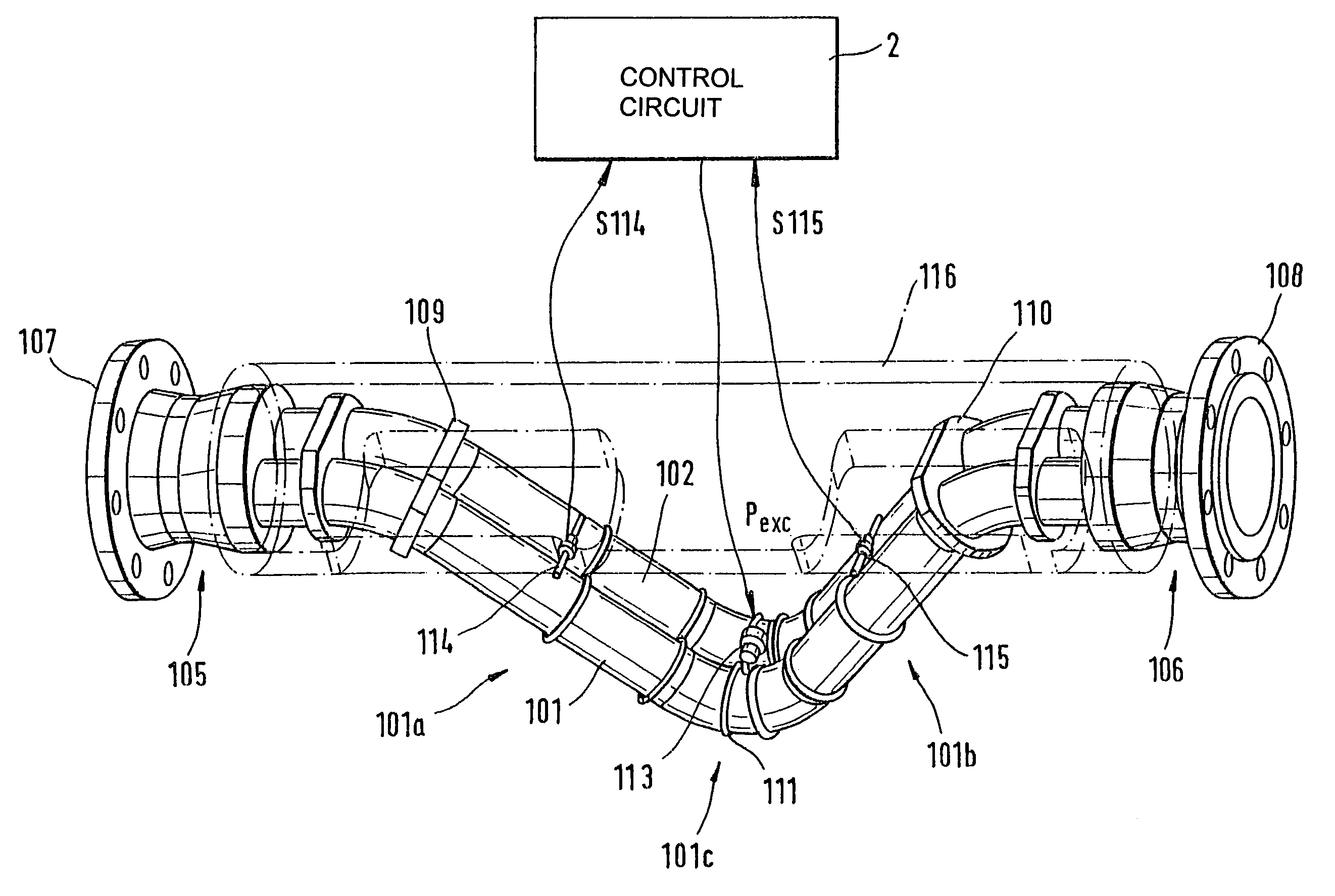
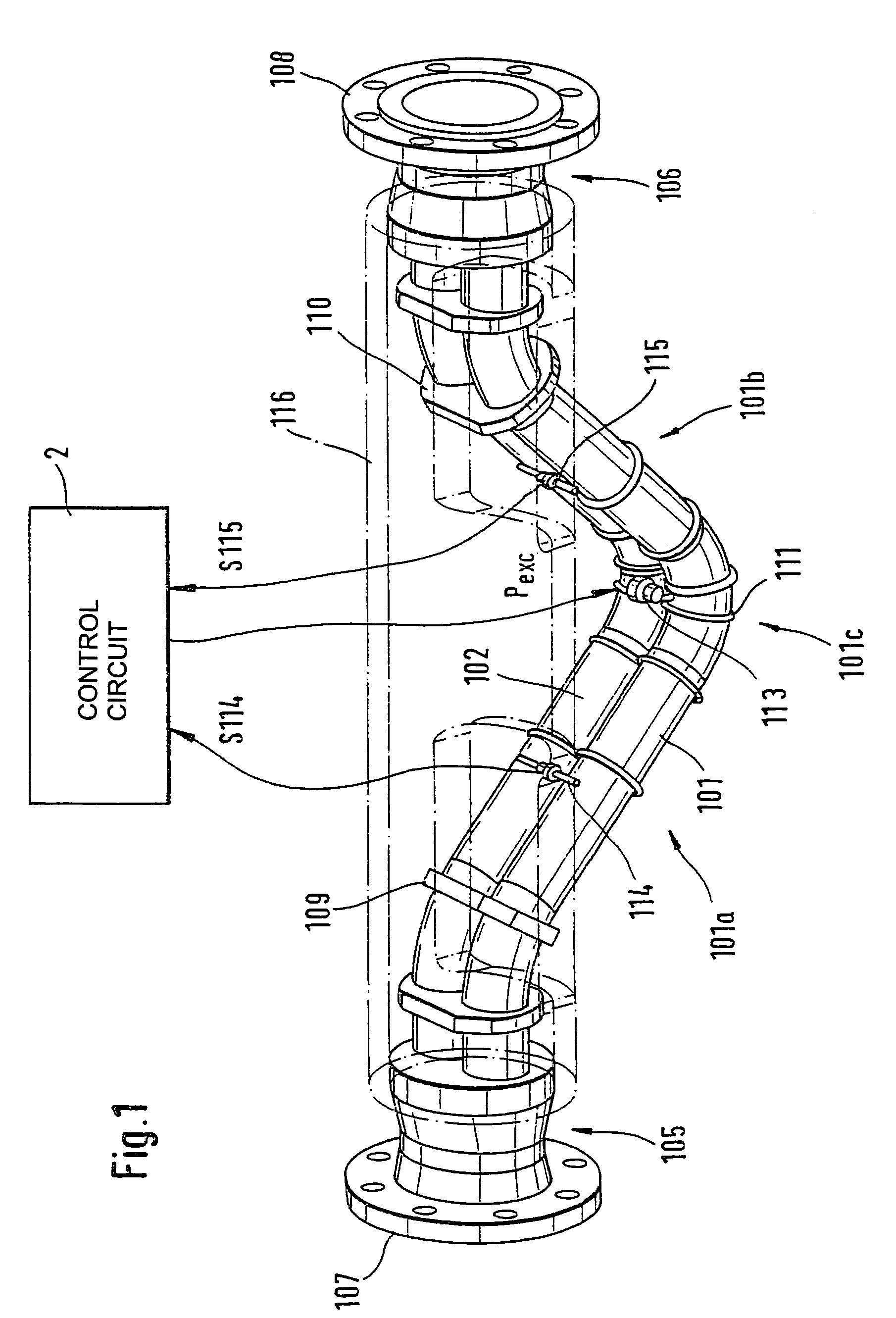
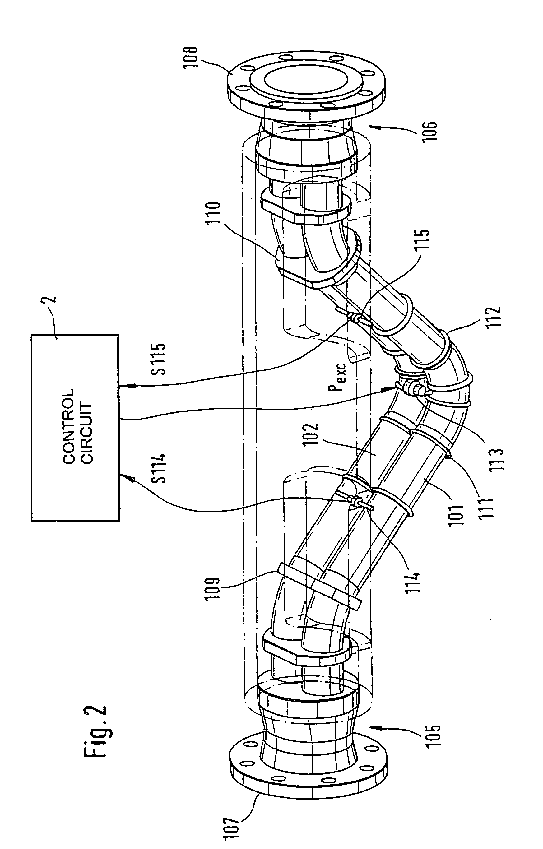
[0035]FIGS. 1 and 2 show embodiments of a vibratory transducer 1 which responds in particular to the mass flow rate of a fluid flowing in a pipe (not shown). If used in a Coriolis mass flowmeter, for example, the transducer will serve to produce Coriolis forces in the fluid flowing therethrough and to sense these forces and convert them into measurement signals suitable for electronic evaluation.

[0036]To conduct the fluid to be measured, transducer 1 comprises a curved first flow t...


PUM

PropertyMeasurementUnit
diameteraaaaaaaaaa
diameteraaaaaaaaaa
mass-flow-rateaaaaaaaaaa

Abstract

The transducer (1) has at least one at least temporarily vibrating flow tube (101) of predeterminable lumen for conducting a fluid. The flow tube (101) communicates with a connected pipe via an inlet tube section (103), ending in an inlet end, and an outlet tube section (104), ending in an outlet end, and in operation performs flexural vibrations about an axis of vibration joining the inlet and outlet ends. The flow tube (101) has at least one arcuate tube section (101c) of predeterminable three-dimensional shape which adjoins a straight tube segment (101a) on the inlet side and a straight tube segment (101b) on the outlet side. At least one stiffening element (111, 112) is fixed directly on or in close proximity to the arcuate tube segment (101c) to stabilize the three-dimensional shape. By means of the at least one stiffening element (111, 112), the cross sensitivity of the transducer (1) is greatly reduced, so that cross talks from pressure to mass flow signals are minimized and the accuracy of the transducer is improved.

Description

CROSS-REFERENCE TO RELATED APPLICATION[0001]This application is based on Provisional Application No. 60 / 330,616, filed on Oct. 26, 2001.FIELD OF THE INVENTION[0002]This invention relates to a vibratory transducer which is particularly suited for a Coriolis mass flowmeter or a Coriolis mass flowmeter-densimeter.BACKGROUND OF THE INVENTION[0003]In measurement and automation technology, the mass flow rate and / or the density of a fluid flowing in a pipe, particularly of a liquid, are frequently determined by means of meters which, using a vibratory transducer and a measuring and control circuit connected thereto, induce reaction forces, particularly Coriolis forces corresponding to the mass flow rate and inertia forces corresponding to the density, in the fluid flowing through the transducer and derive therefrom a measurement signal representing the respective mass flow rate and / or the respective density of the fluid.[0004]Such Coriolis mass flowmeters or Coriolis mass flowmeter-densime...

Claims


Application Information

Patent Timeline
Patent Type & Authority Patents(United States)
IPC IPC(8): G01F1/84G01N17/00G01F1/76G01H11/00G01N9/00
CPCG01F1/8413G01F1/8477G01N2009/006
Inventor WENGER, ALFREDANKLIN, MARTIN
Owner ENDRESS HAUSER FLOWTEC AG
Why Eureka
Try Eureka