At present the operating characteristics of auto-rack cars are not generally considered to be gentle enough to permit this do be done reliably.
That is, a long standing concern has been the frequency of damage claims arising from high accelerations imposed on the lading during
train operation.
Damage due to
dynamic loading in the railcar may tend to arise principally in two ways.
Second, there are vertical, rocking and transverse dynamic responses of the rail road car to track perturbations as transmitted through the rail car suspension.
This slack run-in and run-out can result in significant longitudinal accelerations.
Historically, the need for slack was related, at least in part, to the difficulty of using a steam locomotive to “lift” (that is, move from a standing start) a long string of cars with journal bearings, particularly in
cold weather.
For this type of operation the
coupling speeds can be excessive, resulting in similarly excessive car body accelerations.
For many types of rail road car, humping is now forbidden due to the probability of damaging the lading.
This often less than gentle
habit tends to lead to rather high
impact loads during
coupling at impacts in the 5 m.p.h.
Forces can be particularly severe when there is an
impact between a
low density lading rail road car, such as an auto rack car, and a
high density lading car (or string of cars) such as
coal or grain cars.
While this may be acceptable for
coal or grain, it is undesirably severe for more sensitive lading, such as automobiles or auto parts, paper, and other high value
consumer goods such as household appliances.
However, by eliminating, or reducing, the accumulation of slack, the use of short travel buff gear may tend to reduce the relative longitudinal motion between adjacent rail road cars, and may tend to reduce the associated velocity differentials and accelerations between cars.
AAR Type H couplers are expensive, (and are used for passenger cars), as were the alternate
standard Type CS controlled slack couplers.
647 “Although it was anticipated at one time that the F type coupler might replace the E as the standard freight car coupler, the additional cost of the coupler and its components, and of the car structure required to accommodate it, have led to its being used primarily for special applications”.
Elimination of slack between coupler heads, plus Mini-Buff Gear's high pre-load and limited travel, provide ultralow slack
coupling for multiple-unit well cars and drawbar connected groups of
unit train coal cars.” Notably, unlike vehicle carrying rail cars, coal is unlikely to be damaged by the use of short travel draft gear.
In summary, the 1980 Car &Locomotive Cyclopedia, states at page 669 that the three piece
truck offers “interchangeability,
structural reliability and low first cost but does so at the price of mediocre
ride quality and high cost in terms of car and track maintenance”.
In each case, the design lading tended to be very heavy relative to the rail car weight.
That is, neither coal nor grain tends to be damaged badly by excessive vibration.
Second, when the ratio of lading to car weight increases, a higher proportion of hauling effort goes into hauling lading, as opposed to hauling the deadweight of the railcars themselves.
Similarly, unlike coal or grain, automobiles are relatively fragile, and hence more sensitive to a gentle (or a not so gentle) ride.
As a relatively fragile, high value, high revenue form of lading, it may be desirable to incur a greater expense to obtain superior
ride quality to that suitable for coal or grain.
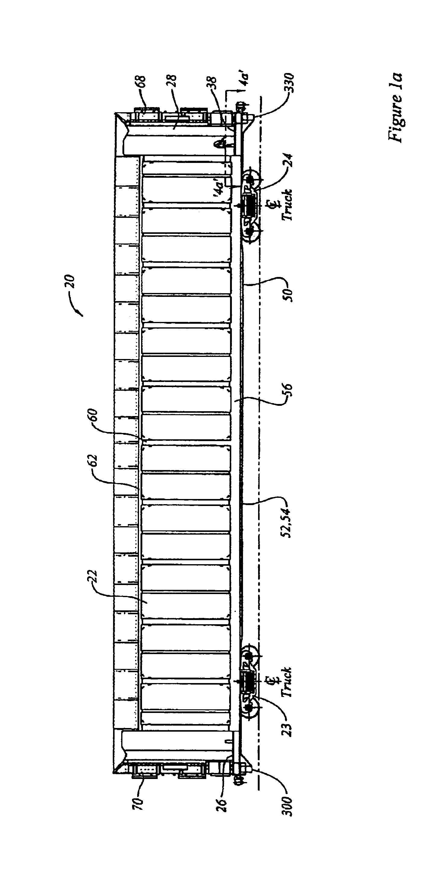
Further, auto rack rail cars tend to be tall, long, and thin, with the upper
deck loads carried at a relatively high location as measured from top of rail.
If softer springs are used, the remaining room for spring travel below the decks may well not be sufficient to provide the desired reserve height.
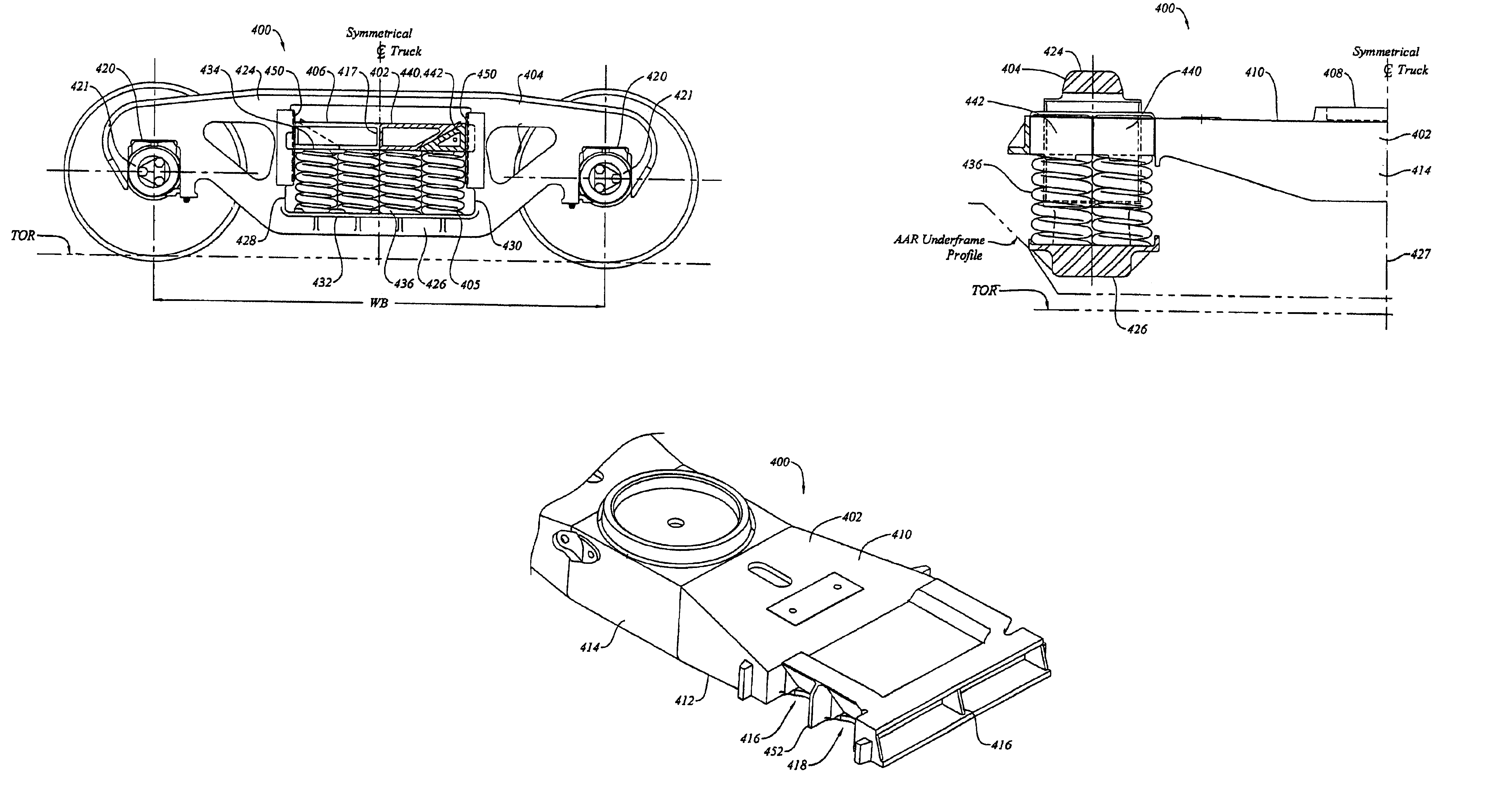
As explained more fully in the description below, the interior trucks of articulated cars tend to be more heavily burdened than the end trucks, primarily because the interior trucks share loads from two adjacent car units, while the couple end trucks only carry loads from one end of one car.
This will tend to cause
lateral deflection of the spring group, and will tend to generate a squeezing force on opposite
diagonal sides of the wedges, causing them to tend to bear against the side frame columns.
This increase in
wheelbase length may tend also to be benign in terms of wheel loading equalisation.

