Fuel injection control devices for internal combustion engines

a technology of control device and internal combustion engine, which is applied in the direction of electric control, fuel injecting pump, machine/engine, etc., can solve the problems of increasing the diameter of the fuel spray particle, the inability to effectively achieve uniform combustion, and the inability etc., to improve engine performance, fuel economy, and engine power.

Inactive Publication Date: 2005-07-26
AISAN IND CO LTD
View PDF15 Cites 13 Cited by
  • Summary
  • Abstract
  • Description
  • Claims
  • Application Information

AI Technical Summary

Benefits of technology

[0010]The present invention has been accomplished in view of the above-mentioned circumstances and it is a first object of the invention to provide a fuel injection control device for internal combustion engines which change a combustion pattern according to a

Problems solved by technology

Specifically, it is impossible to effectively achieve the uniform combustion and to select one from two or more combustion patterns, so that engine performances could not be improved.
This results in an increase in diameter of a fuel spray particle, which decreases resistance of the air to the fuel spray and thus increases a fuel spray travel (distance).
Accordingly, this device could not easily shorten the fue

Method used


Image

  • Fuel injection control devices for internal combustion engines
  • Fuel injection control devices for internal combustion engines
  • Fuel injection control devices for internal combustion engines

Examples


first embodiment

[0044][First Embodiment]

[0045]A fuel injection control device for an internal combustion engine according to a first embodiment of the present invention will be described below in detail with reference to accompanying drawings.

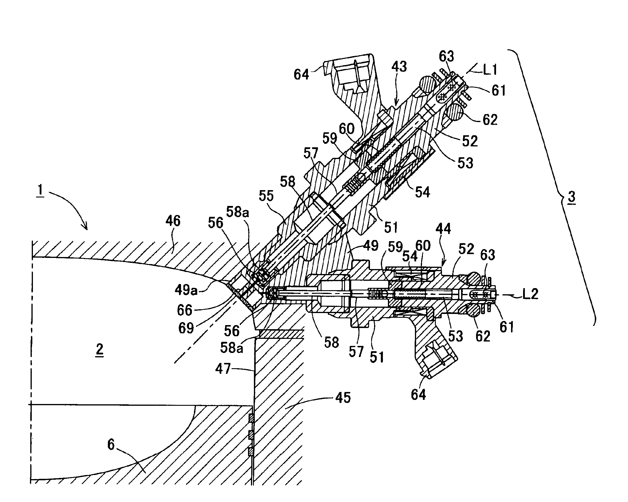
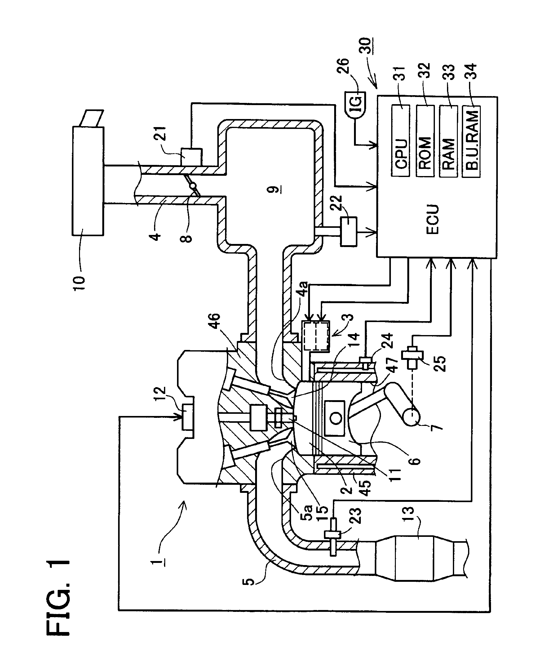
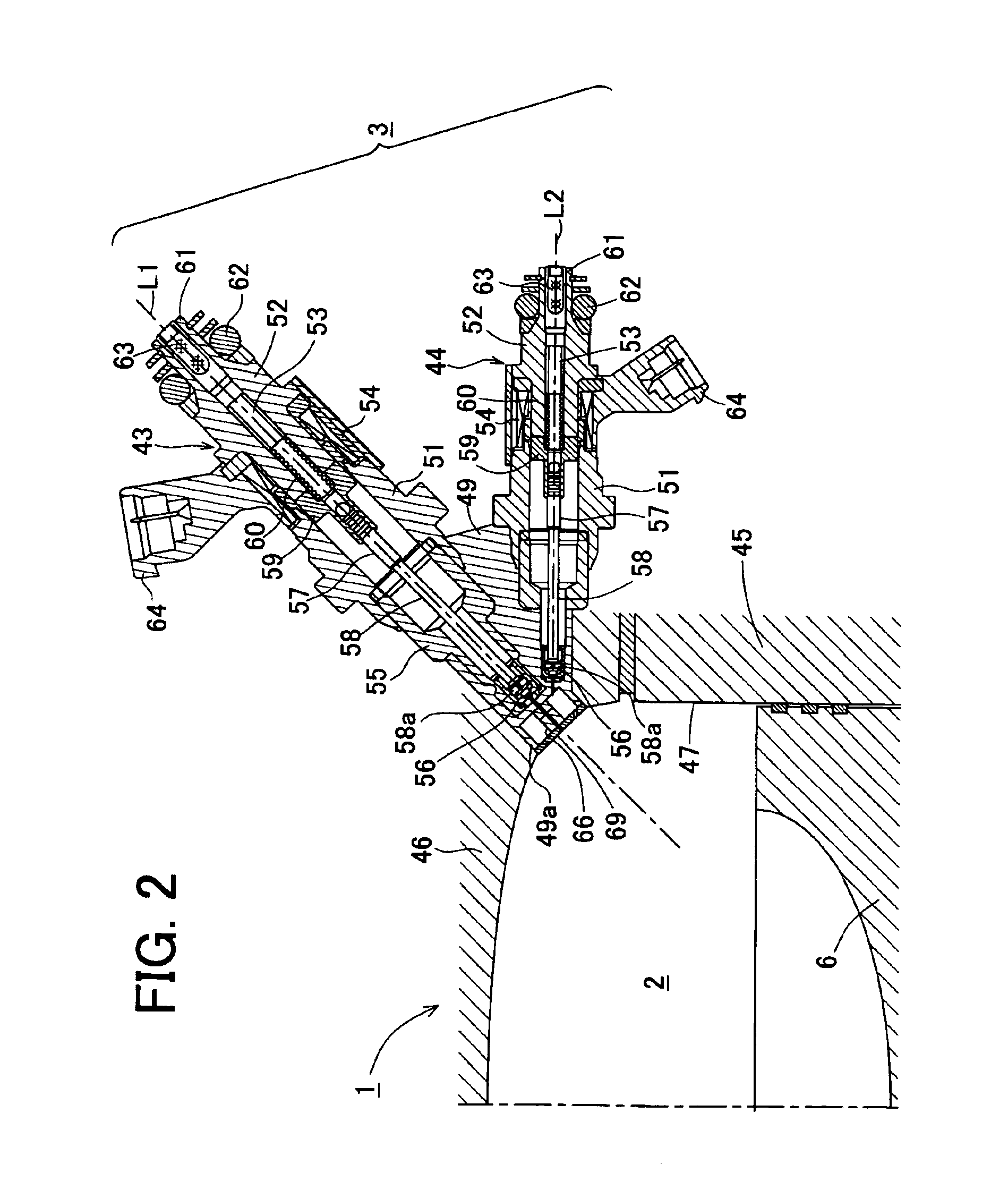
[0046]FIG. 1 is a schematic construction diagram of a direct injection type internal combustion engine system (hereinafter referred to as the “direct injection type engine system”) including a fuel injection control device for an internal combustion engine embodying the present invention. A direct injection type engine system mounted on an automobile includes a reciprocating multi-cylinder engine 1 of a known structure. A direct injection type fuel injection device (simply “fuel injection device” hereinafter) 3 is installed in each of combustion chambers 2 which are formed respectively in the cylinders of the engine 1. The fuel injection device 3 is constructed so as to inject fuel and air directly into the associated combustion chamber 2. In the engine 1, a c...

second embodiment

[0108][Second Embodiment]

[0109]Next, a fuel injection control device for an internal combustion engine according to a second embodiment of the present invention will be described in detail below with reference to associated drawings.

[0110]In the subsequent embodiments including the second embodiment, the same components as in the first embodiment are identified by the same reference numerals as those in the first embodiment and explanations thereof will be omitted. The following description will mainly be given of different points.

[0111]The second embodiment differs from the first embodiment in the construction using a fuel heating type fuel injection device and a control device thereof, instead of using the air blast type fuel injection device 3. FIG. 25 is a conceptual construction diagram showing a heating type fuel injection device 101 and an associated electric wiring and fuel pipe. As shown in FIG. 25, the heating type fuel injection device 101 includes a fuel injection valve ...

third embodiment

[0124][Third Embodiment]

[0125]Next, a fuel injection control device for an internal combustion engine according to a third embodiment of the present invention will be described in detail below with reference to associated drawings.

[0126]This embodiment differs from the first embodiment in the construction using a variable fuel pressure type fuel injection device and a control device thereof, instead of using the air blast type fuel injection device 3. FIG. 28 is a conceptual construction diagram showing a variable fuel pressure type fuel injection device 111 and an associated electric wiring and fuel pipe. As shown in FIG. 28, the variable fuel pressure type fuel injection device 111 includes a fuel injection valve 112 which is formed with a fuel injection orifice 102a opening into the combustion chamber 2 and for injecting pressurized fuel into the combustion chamber 2 from the orifice 102a, and a variable pressure regulator 113 serving as fuel pressure changing means for changing ...


PUM


Abstract

A fuel injection device includes a fuel injection valve for injecting fuel through a fuel injection orifice opening into a combustion chamber, an air injection valve for injecting air through an air injection orifice opening into the combustion chamber, sensors for detecting an operating condition of an engine, and an electronic control unit (ECU) for controlling the fuel injection valve and the air injection valve. Orientations of the air injection orifice and the fuel injection orifice are determined to make an air jet collide with a fuel spray. The ECU controls the fuel injection valve based on the operating condition detected by the sensors to control spray velocity, spray particle diameter, spray angle, etc. of the fuel to be injected through the fuel injection orifice, and at least one of an air injection timing and an air injection period of air injection to be performed by the air injection valve.

Description

BACKGROUND OF THE INVENTION[0001]1. Field of the Invention[0002]The present invention relates to a fuel injection control device for a direct injection type internal combustion engine adapted to directly inject fuel into a combustion chamber in an internal combustion engine. More particularly, the present invention is concerned with a fuel injection control device constructed such that a fuel spray is supplied in conformity with an operating condition of the internal combustion engine.[0003]2. Description of Related Art[0004]Relating to direct injection type internal combustion engines, heretofore, fuel injection control devices adapted to supply fuel in a spray form appropriate for an operating condition of the engines are disclosed for example in Japanese patent unexamined publication No. 2000-97030 (pages 4-6 and FIG. 3), Japanese patent unexamined publication No. Hei 10-318096 (page 9 and FIG. 7), and Japanese patent unexamined publication No. 2002-161790 (pages 2-5 and FIGS. 1-...

Claims


Application Information

Patent Timeline
IPC IPC(8): F02M53/06F02M67/12F02M67/00F02M67/02F02M53/00F02M51/06F02D41/02F02D41/34F02M53/02F02M61/14F02M61/18
CPCF02M51/0671F02M53/06F02M67/02F02M67/12
Inventor HAYAKAWA, MASAYAYONESHIGE, KAZUHIRO
Owner AISAN IND CO LTD
Why Eureka
Try Eureka