Magnetic recording medium comprising a magnetic layer having specific thickness, surface roughness and friction coefficient

a magnetic layer and recording medium technology, applied in the field of magnetic recording mediums, can solve the problems of increased error rate, decreased output, and deterioration of the durability of the magnetic recording media, and achieve the effect of reducing the spacing loss of the medium and reducing the error rate through suppression of off-track

Inactive Publication Date: 2005-07-26
FUJIFILM CORP
View PDF33 Cites 110 Cited by
  • Summary
  • Abstract
  • Description
  • Claims
  • Application Information

AI Technical Summary

Benefits of technology

[0016]One object of the present invention is to provide a magnetic recording medium which can decrease the spacing loss of the medium to be used with the MR head, and reduce the error rate through the suppression of the off-track caused by the meandering of the medium.
[0017]Another object of the present invention is to provide a magnetic recording medium which can reduce the wearing of the MR head to be used in combination with the magnetic recording medium.
[0018]To achieve the above objects, extensive research has been done. As a result, it has been found that, when a difference of the height of the highest projection (P1) and the averaged height of the projections (P0) (P1−P0) is smaller than a specific value, and the difference of the height of the highest projection (P1) and the height of the 20th highest projection P20 (P1-P20) is also smaller than a specific value, a spacing loss is decreased, and further that, when a ratio of μmSL to μmSUS [(μmSL) / (μmSUS)] and a ratio of μmSL to μBSUS [(μmSL) / (μBSUS)], wherein μmSL is a coefficient of kinetic friction (hereinafter referred to as “coefficient of friction”) between a magnetic layer and a slider material (e.g. alumina / titania / carbide), μmSUS is a coefficient of friction between the magnetic layer and a stainless steel (SUS304) (hereinafter referred to as “SUS”), and μBSUS is a coefficient of friction between the backcoat layer and SUS, are controlled to specific values, the off-track caused by the meandering of the magnetic tape is suppressed and thus an error rate is improved. The effect to improve the error rate through the decrease of the off-track is particularly remarkable when the track width is 15 μm or less.

Problems solved by technology

When the thickness of the magnetic layer is reduced to 0.3 μm or less, the durability of the magnetic recording media tend to deteriorate.
Thus, if the magnetic layer has large projections, a half width value of output peak (hereinafter referred to as “PW50”) may increase or the output may decrease due to the spacing loss so that an error rate may increase.
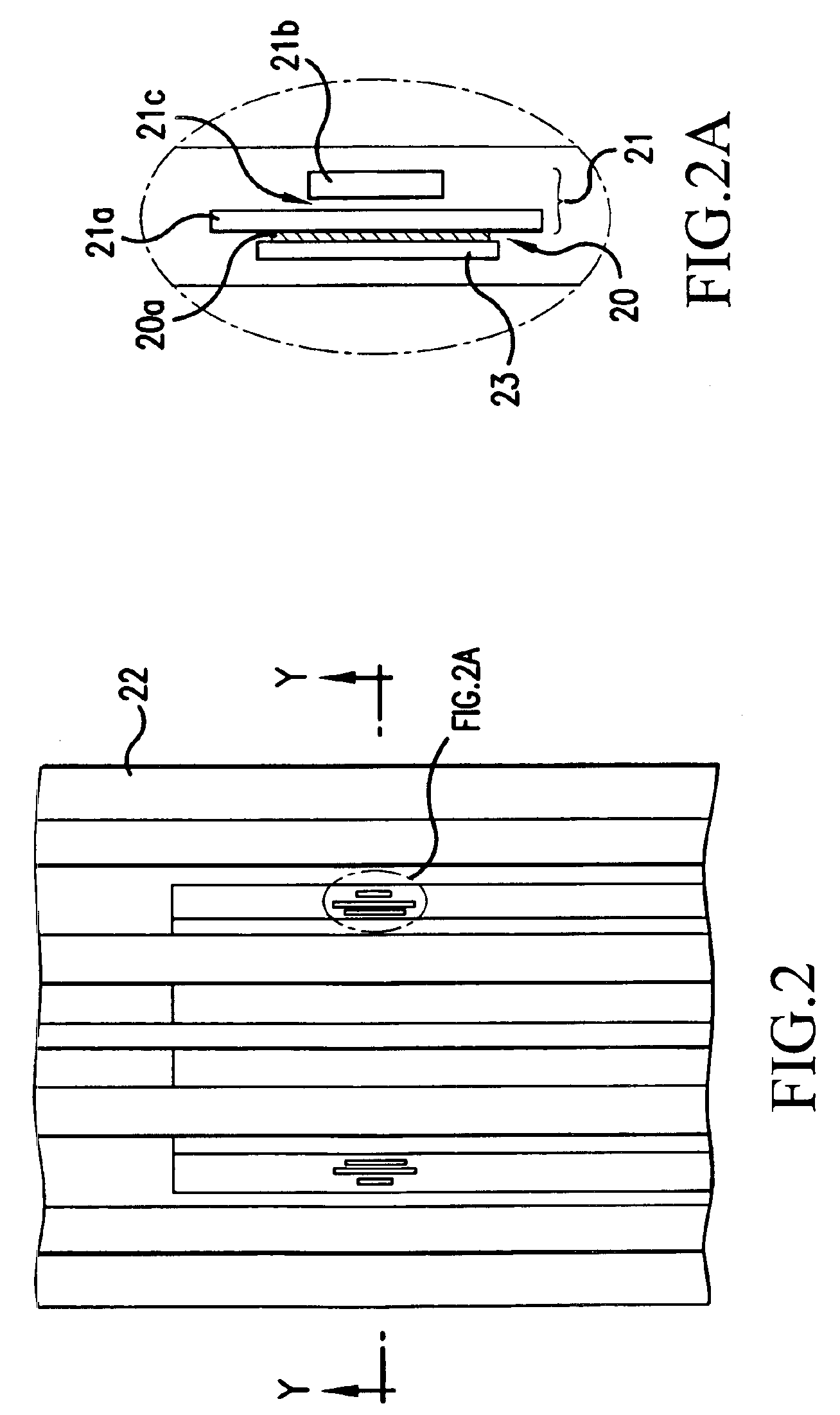
Furthermore, since the MR element 20a of the MR head 20 comprises a very thin film, it is easily worn out.
However, if a coefficient of friction of the magnetic layer or the backcoat layer against a slider material (for example, alumina / titania / carbide, etc.) or a material of guide rollers is insufficiently optimized, the magnetic tape meanders so that the tracking may deviate (off-track), PW50 may increase or the output may decrease.
Therefore, the error rate may increase.

Method used


Image

  • Magnetic recording medium comprising a magnetic layer having specific thickness, surface roughness and friction coefficient
  • Magnetic recording medium comprising a magnetic layer having specific thickness, surface roughness and friction coefficient
  • Magnetic recording medium comprising a magnetic layer having specific thickness, surface roughness and friction coefficient

Examples


example 1

[0110]

(1)Iron oxide powder (particle size: 0.11 × 0.02 μm)68partsα-Alumina (particle size: 0.07 μm)8partsCarbon black (particle size: 25 nm;24partsoil absorption: 55 g / cc)Stearic acid2.0partsVinyl chloride-hydroxypropyl acrylate copolymer8.8parts(—SO3Na group content: 0.7 × 10⁻⁴ eq. / g)Polyesterpoyurethane resin4.4parts(Tg: 40° C., —SO3Na group content: 1 × 10⁻⁴ eq. / g)Cyclohexanone25partsMethyl ethyl ketone40partsToluene10parts(2)Butyl stearate1partCyclohexanone70partsMethyl ethyl ketone50partsToluene20parts(3)Polyisocyanate4.4parts(Colonate L manufactured by Nippon Polyurethane)Cyclohexanone10partsMethyl ethyl ketone15partsToluene10parts(A)Ferromagnetic iron metal powder100parts(Co / Fe: 20 atomic %, Y / (Fe + Co): 3 atomic %,Al / (Fe + Co): 5 wt. %, Ca / Fe: 0 wt. %;σs: 155 A · m2 / kg, Hc: 149.6 kA / m, pH: 9.4,major axis length: 0.10 μm)Vinyl chloride-hydroxypropyl acrylate copolymer12.3parts(—SO3Na group content: 0.7 × 10⁻⁴ eq. / g)Polyesterpoyurethane resin5.5parts(—SO3Na group content: 1 × ...

examples 2-10

[0124]A magnetic tape for computer was produced in the same manner as in Example 1 except that a part of the conditions were changed as shown in Tables 1, 2 and 3.


PUM

PropertyMeasurementUnit
surface roughness Raaaaaaaaaaa
thicknessaaaaaaaaaa
thicknessaaaaaaaaaa

Abstract

A magnetic recording medium comprising a non-magnetic support, at least one primer layer formed on one surface of the non-magnetic support, a magnetic layer formed on the primer layer, and a backcoat layer formed on the other surface of the non-magnetic support, wherein the magnetic layer has a thickness of 0.30 μm or less and a centerline average surface roughness Ra of 3.2 nm or less, and (P1−P0) is 30 nm or less and (P1-P20) is 5 nm or less in which P0 is an averaged height of projections of the magnetic layer, and P1, P2, - - - and P20 are heights of the highest, the second highest, - - - and the 20th highest projections of the magnetic layer, respectively.

Description

[0001]This application is a Divisional of application Ser. No. 09 / 984,982, filed on Oct. 31, 2001 now U.S. Pat. No. 6,780,531, the entire contents of which are hereby incorporated by reference and for which priority is claimed under 35 U.S.C. § 120; and this application claims priority of application Ser. No. 333928 / 2000 filed in Japan on Oct. 31, 2000 under 35 U.S.C. § 119.BACKGROUND OF THE INVENTION[0002]1. Field of the Invention[0003]The present invention relates to a magnetic recording medium having a high recording capacity, a high access speed and a high transmission speed. In particular, the present invention relates to a magnetic recording medium for data-backup, which records and reads data with a reading head comprising a magnetoresistance element (hereinafter referred to as “MR head”).[0004]2. Prior Art[0005]Magnetic tapes have various applications such as audio tapes, videotapes, computer tapes, etc. In particular, in the field of magnetic tapes for data-backup, a tape h...

Claims


Application Information

Patent Timeline
Patent Type & Authority Patents(United States)
IPC IPC(8): G11B5/78G11B5/73G11B5/70G11B5/62G11B5/735G11B5/74G11B5/008
CPCG11B5/70G11B5/7305G11B5/735G11B5/78G11B5/00813Y10S428/90G11B5/7356G11B5/7368
Inventor TANI, MASAKAZUMAKITA, YOSHIYUKIYOSHIMOTO, NORIHISAYOSHIDA, KENICHIRO
Owner FUJIFILM CORP
Why Eureka
Try Eureka