
Thermally high conductive HV connector for a mono-polar CT tube

a technology of ct tubes and connectors, applied in the field of imaging systems, can solve the problems of high voltage insulating materials such as epoxy, poor thermal conductivity of high voltage electric cables, and large amount of heat generated in x-ray tubes, and achieve the effect of reducing partial discharge activities

Inactive Publication Date: 2005-07-26
GE MEDICAL SYST GLOBAL TECH CO LLC
View PDF7 Cites 9 Cited by
  • Summary
  • Abstract
  • Description
  • Claims
  • Application Information

AI Technical Summary

Benefits of technology

[0017]One advantage of the present invention is that the Faraday Cup offers substantial relief in local electric fields in the vicinity of HV wiring joints, which reduces partial discharge activities. Another advantage is thermal management with different thermal conductivities of gasket and epoxy based materials.

Problems solved by technology

Generally, high voltage insulating materials, such as epoxy, also tend to be very poor thermal conductors.
This creates undesirable results when an HV connector assembly is directly attached to an X-ray tube, such as across an end thereof.
As stated above, a large quantity of heat is generated in the X-ray tube, as an undesired byproduct of X-ray generation.
Because of its poor thermal conductive properties, this insulator serves as a heat barrier such that a substantial amount of heat tends to accumulate proximate to the connector.
Resultantly, the temperature limits of the connector insulation may be readily exceeded, such that the steady state performance of an X-ray tube is limited.
Mono-polar systems have numerous challenges in terms of HV clearance, discharge activities due to a much higher operating voltage, and constrained dimensions.
Several reliability and performance issues have been identified, however, due to thermal stress and material degradation of these conical devices.
Conical HV insulation is therefore generally not a viable option for high power tubes.
One of major challenges an HV connector faces is HV integrity under high power conditions.
For a continuous high power application, connector temperatures may exceed material limits.
Consequently a catastrophic failure may occur through electric breakdown due to thermal runaway or long term discharges from associated material degradation, related to excessive temperatures.
Typical HV solutions often have difficulties handling high temperature scenarios including temperatures in excess of 150° C. Components that include EPR rubber, which is only rated at 105° C. continuously, are of great concern for such applications.
The disadvantages associated with current X-ray systems have made it apparent that a new technique for HV connection to X-ray systems is needed.

Method used


Image

  • Thermally high conductive HV connector for a mono-polar CT tube
  • Thermally high conductive HV connector for a mono-polar CT tube
  • Thermally high conductive HV connector for a mono-polar CT tube

Examples


Embodiment Construction

[0026]The present invention is illustrated with respect to an HV connector system, particularly suited to the medical field. The present invention is, however, applicable to various other uses that may require HV connector systems, as will be understood by one skilled in the art.

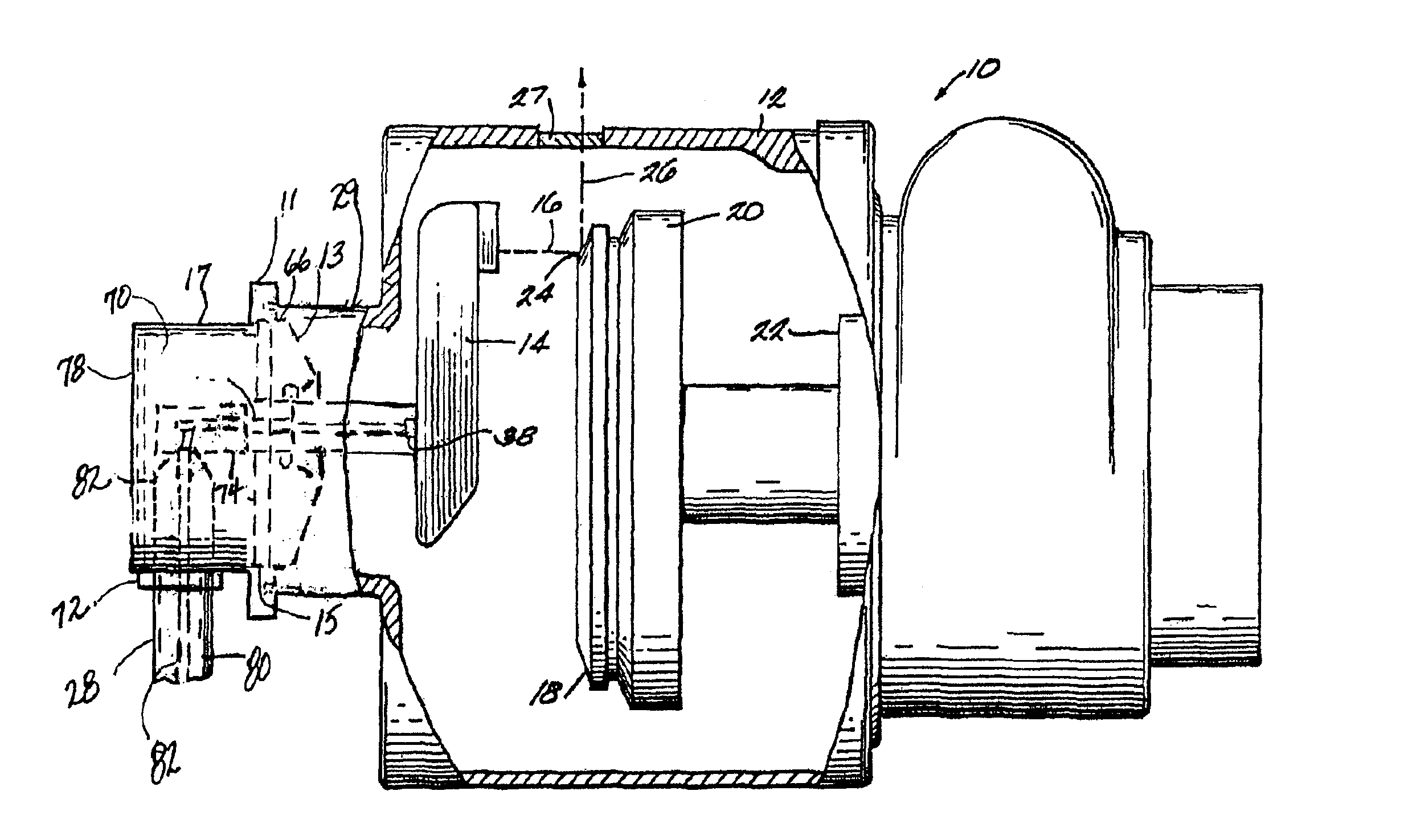
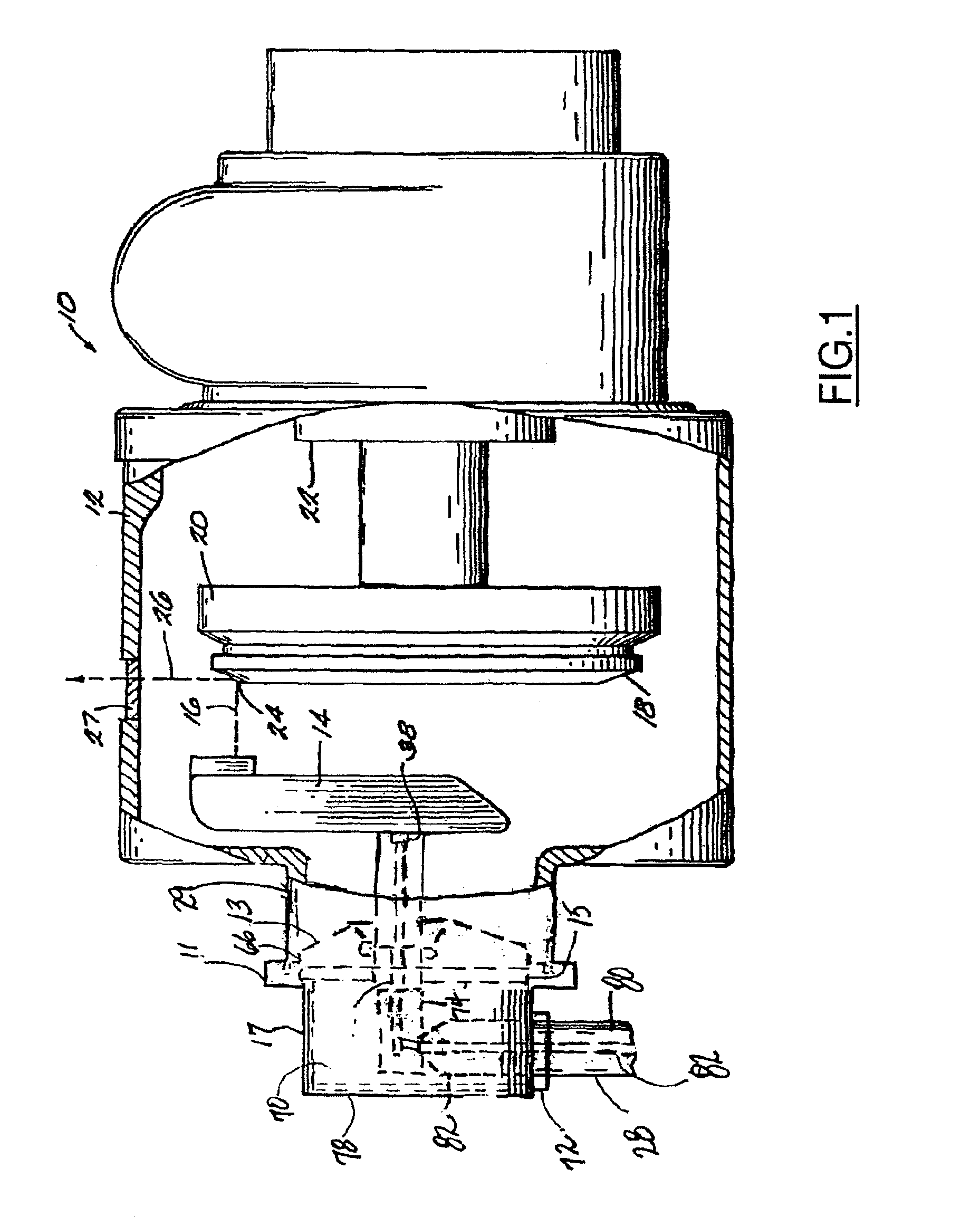
[0027]Referring to FIG. 1, an X-ray tube system 10 (X-ray device) including an HV system 11 coupled to a metal housing 12, which supports other X-ray tube components, in accordance with a preferred embodiment of the present invention, is illustrated.

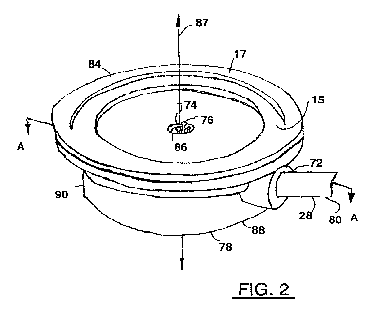
[0028]The HV system 11, which includes an HV insulator 13, a gasket 15, and an HV connector 17, will be discussed in detail with regards to FIGS. 2, 3 and 3A.

[0029]The metal housing 12 includes a cathode 14, and a protective vacuum enclosure for the cathode 14. The cathode 14 directs a high energy beam of electrons 16 onto a target track 18 of an anode 20, which includes a refractory metal disk and is continually rotated by means of a conventional mounting and dr...


PUM


Abstract

An HV connector for high power X-ray device consists of thermally conductive epoxy, cable terminal, faraday cup, spring-loaded contact, and lead lined housing. The thermally conductive epoxy includes fillers. The epoxy can also be loaded with gravels of similar materials. A Faraday cup is included in the center area to offer electric field relief. Spring-loaded contacts are included for the easiness of pin alignment and robustness of handling. An efficient thermal management solution is accomplished through proper selection of thermal conductivities of gasket and epoxy.

Description

RELATED APPLICATION[0001]The present invention is related to application Ser. No. 10 / 294,857 entitled “HV System For A Mono-Polar Ct Tube” filed simultaneously herewith and incorporated by reference herein.TECHNICAL FIELD[0002]The present invention relates generally to imaging systems and more particularly to an improved apparatus for connecting a high voltage (HV) electric cable to an X-ray tube.BACKGROUND[0003]Typical rotating anode X-ray tubes include a beam of electrons directed through a vacuum and across a very high voltage (on the order of 100 kilovolts) from a cathode to a focal spot position on an anode. X-rays are generated as electrons strike the anode, which typically includes a tungsten target track, which is rotated at a high velocity.[0004]The conversion efficiency of X-ray tubes is relatively low, i.e. typically less than 1% of the total power input. The remainder is converted to thermal energy or heat. Accordingly, heat removal, or other effective procedures for man...

Claims


Application Information

Patent Timeline
IPC IPC(8): A61B6/00G21G4/00H01J35/10H01J35/00H01R13/46H05G1/08H05G1/10H05G1/12H05G1/02H05G1/00H01J35/02
CPCH01J35/025H01J2235/0233
Inventor TANG, LIANGSUBRAYA, MADHUSUDHANA TALNERUNEITZKE, PAUL
Owner GE MEDICAL SYST GLOBAL TECH CO LLC
Learn More