Building closure, such as a door or window, constructed to resist an explosive blast

a technology for building closures and explosive blasts, applied in the direction of building components, constructions, shock proofing, etc., can solve the problems of not being directly suitable for use, the construction disclosed in the german patent de 37 05 401, and the rather large dimension of the fixed jamb frame, etc., to achieve economic production and installation without great effort, expense or difficulty

Inactive Publication Date: 2005-08-02
SALZER SICHERHEITSTECHN
View PDF11 Cites 22 Cited by
  • Summary
  • Abstract
  • Description
  • Claims
  • Application Information

AI Technical Summary

Benefits of technology

[0012]Furthermore, preferably at least one damping element is respectively arranged on each one of the opposite sides of the frame elements between mutually facing countersupport surfaces. These two opposite damping elements achieve a damping effect in opposite directions by plastically deforming when respective forces are applied to the building closure in opposite directions.
[0018]According to the invention, beginning from a jamb frame construction of a conventional type, the two opposite countersupport or abutment surfaces that face toward each other make it possible to achieve very good explosive blast resisting properties, whereby simultaneously the structural complexity and expense is relatively low and the assembly and installation is relatively easy. It is not necessary, as it is in the German Patent DE 37 05 401 for example, that flanges of the jamb frame enclose a central web that is rigidly connected with the sill or edge of the opening. To the contrary, it is a general characteristic of the preferred embodiment of the present invention, that a part of the jamb frame extends into a groove-shaped recess or area of the sill that bounds the opening, whereby portions of the sill bound the two opposite sides or edges of this groove-shaped recess. These two opposite sides of the groove-shaped recess form the countersupport or abutment surfaces and serve to introduce the arising forces into building components, e.g. the masonry wall of the building, in the event of a force being applied to the building closure.
[0029]In comparison to securing means such as expansion bolts, dowels, or bolt anchors, which provide a more or less point-wise force introduction into the wall, the inventive force introduction surface provided by the above mentioned brackets achieves a distributed force introduction over a large surface area of the building wall or the like. Also, this force introduction area can easily be enlarged to the required size, so that the danger of the building closure becoming loose, ripping out, or being pressed into the building opening is reliably excluded, even in connection with masonry walls or other walls that have a relatively low load bearing capacity. The number of these brackets and their particular dimensions can be selected or adjusted depending on the actual requirements of a particular application. It is also possible to provide respective support shanks on both opposite ends of the brackets, to achieve a supporting and force introduction both on the interior side as well as the exterior side of the building. In this manner, the forces arising both from the positive pressure wave as well as from the negative pressure wave can be reliably and surely taken up and introduced into the building wall or the like.

Problems solved by technology

It could be said, however, that the known construction suffers the disadvantage that it requires a rather large dimension of the fixed jamb frame in a direction perpendicular to the plane defined by the filler panel.
Moreover, the fixed jamb frame cannot be embodied in a one-piece manner, because, to facilitate the installation, at least one flange can only be connected with the remaining building closure during the installation.
Furthermore, the construction disclosed in German Patent DE 37 05 401 is not directly suitable for use in connection with a pivoting openable building closure having a movable panel frame swingably supported in the fixed jamb frame.
This previously known construction according to DE 37 44 816 is also not directly suitable for use in connection with a movable panel or sash frame that is pivotally or tiltably supported in a fixed jamb frame.
Also in view of aesthetic considerations, this known construction is not acceptable, because the planes defined by the filler panel surfaces are all arranged in front of the furthest protruding plane of the wall or portion of the building bounding the opening.

Method used


Image

  • Building closure, such as a door or window, constructed to resist an explosive blast
  • Building closure, such as a door or window, constructed to resist an explosive blast
  • Building closure, such as a door or window, constructed to resist an explosive blast

Examples


Embodiment Construction

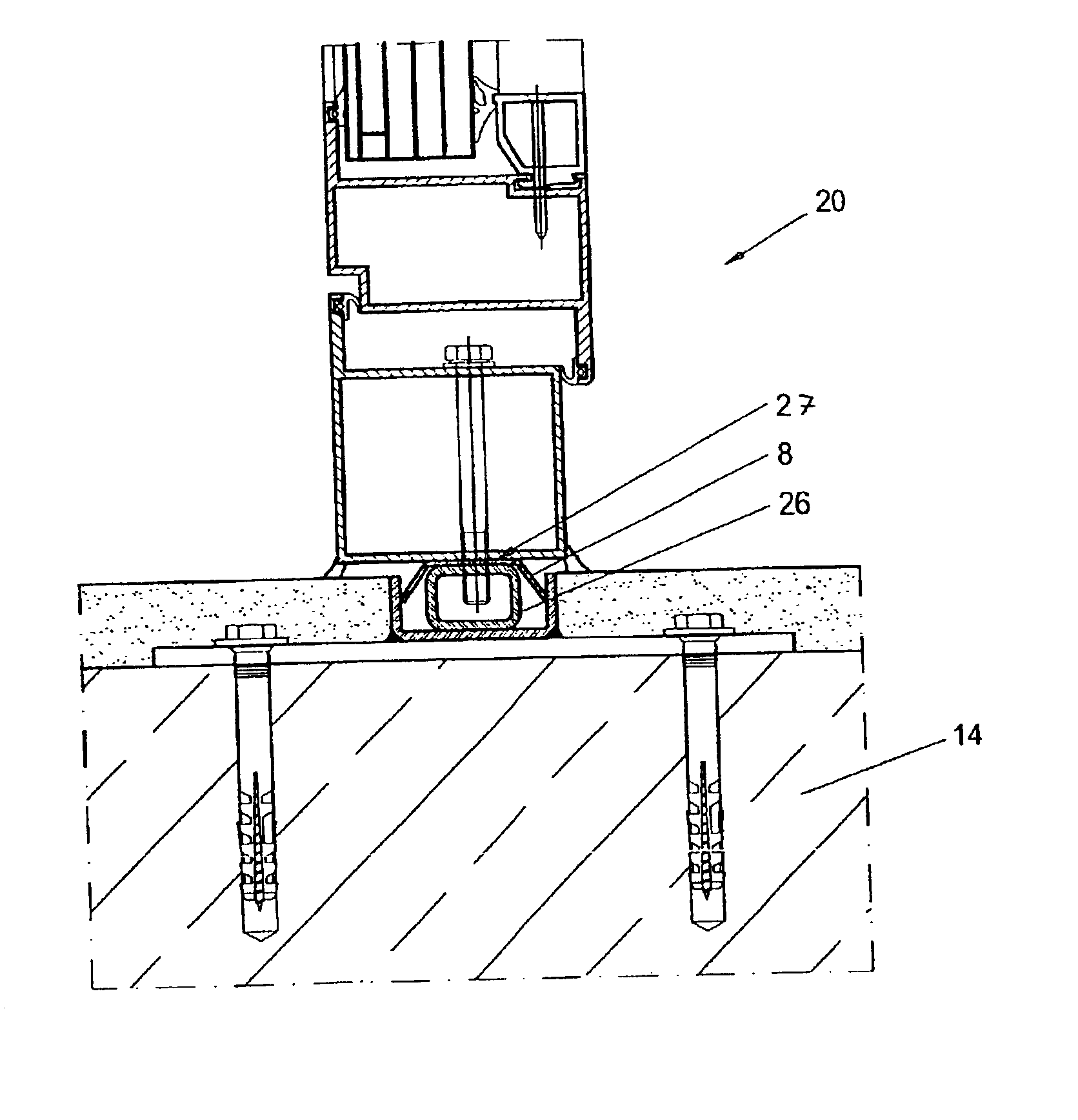
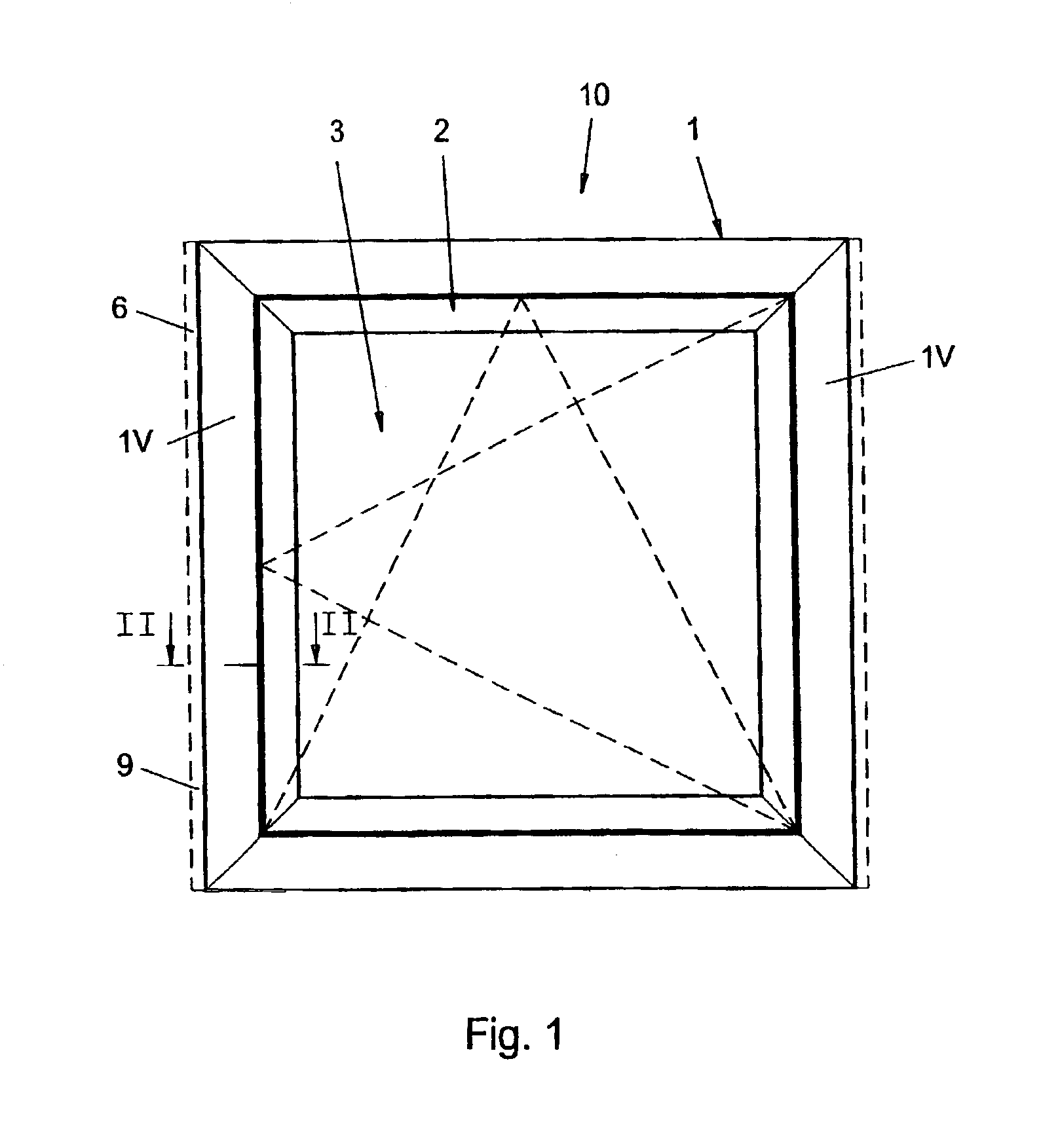
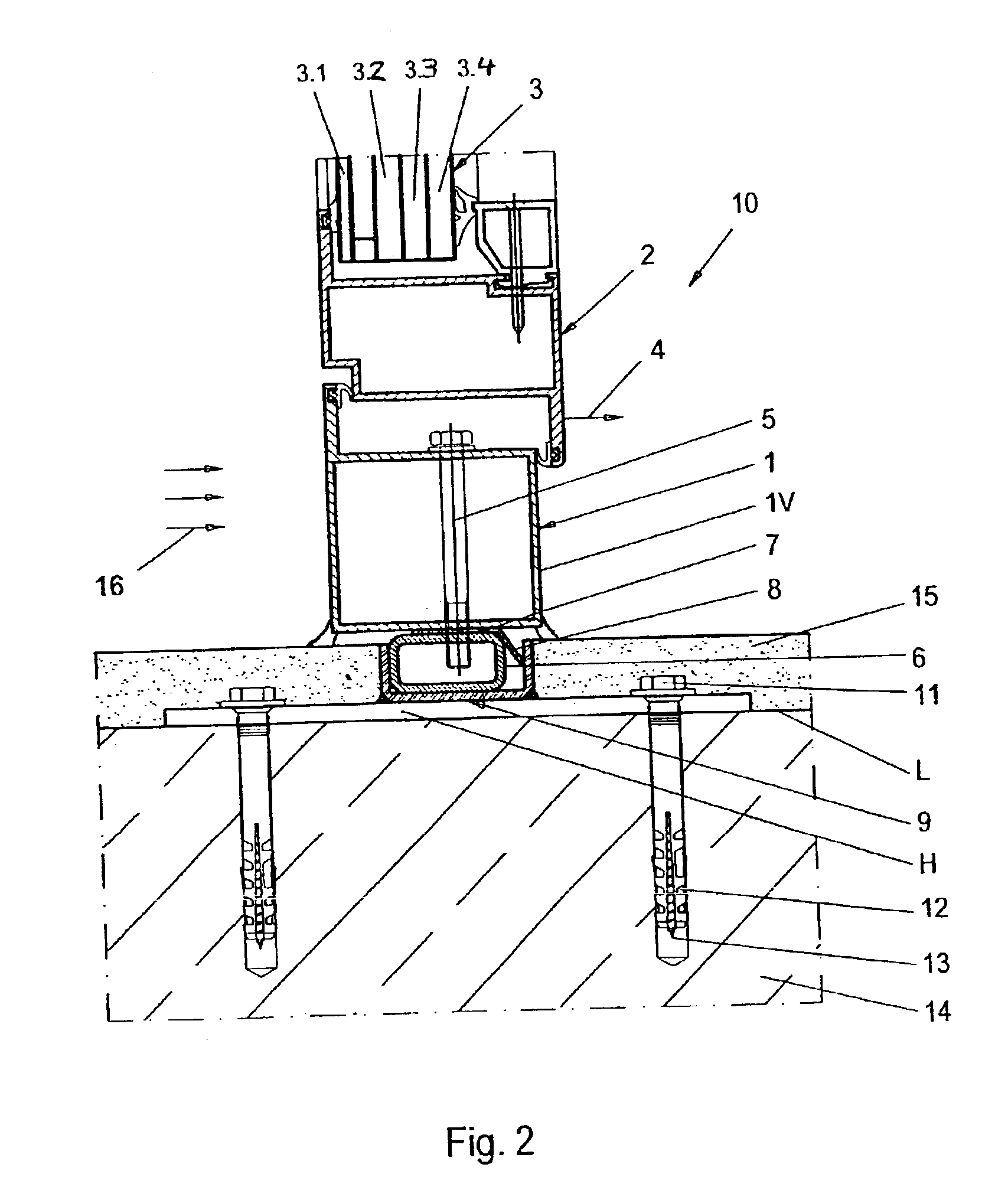
[0038]A building closure arrangement 10 shown in FIGS. 1 and 2 is particularly embodied as an explosion resistant window arrangement 10 that is secured in an opening of a building facade, e.g. a building wall, so as to close the opening. The building closure arrangement or window arrangement 10 comprises a fixed jamb frame 1 that is secured to the boundaries of the building wall that bound the opening, a movable sash frame 2 that is pivotably or tiltably supported in the fixed jamb frame 1, as well as a filler panel 3 that is held and carried by the sash frame 2. The filler panel 3, for example, is a high pressure resistant bulletproof glass arrangement including four individual layers 3,1, 3.2, 3.3 and 3.4 of bulletproof glass panes. The structure and the cooperative arrangement of the bulletproof glass filler panel 3, the movable sash frame 2, and the fixed jamb frame 1, relative to each other, can be according to any conventionally known teachings. Therefore, these features are n...


PUM


Abstract

An opening in a building wall is closed by a building closure such as a window or door. A mounting part of the closure arrangement is received in a space between two countersupport surfaces formed by a U-channel or opposite L-members that protrude perpendicularly from the sill or jamb surface of the wall bounding the opening. Mounting brackets secure the U-channel or L-members to the wall. On one or both sides, a respective damping element is interposed between the mounting part and the respective adjacent countersupport surface. The damping element may be a plastically deformable metal strip. When an explosion force acts on the closure arrangement, the damping element is first plastically deformed to absorb energy, before the remaining force is transmitted into the building wall. The two damping elements on opposite sides damp forces from the positive and negative pressure waves of the explosion.

Description

PRIORITY CLAIM[0001]This application is based on and claims the priority under 35 U.S.C. §119 of German Patent Application 102 20 832.8, filed on May 8, 2002, the entire disclosure of which is incorporated herein by reference.FIELD OF THE INVENTION[0002]The invention relates to a building closure, such as a door or window, that is constructed to resist and thereby withstand and retard an explosive blast. The building closure generally includes a filler panel surrounded and supported by frame elements, which are connected in a force-transmitting manner to the sill or jamb surface of an opening in the wall of a building. At least one damping element is provided to achieve a damping effect when an explosive blast pressure is exerted on the building closure panel.BACKGROUND INFORMATION[0003]In the present application, the term “building closure” generally refers to windows and doors of a building, but also other types of flat or surfacial closure elements, such as facade elements, for e...

Claims


Application Information

Patent Timeline
Patent Type & Authority Patents(United States)
IPC IPC(8): E06B1/56E06B5/12E06B5/10E06B1/60
CPCE06B1/6084E06B5/12E06B1/6015
Inventor SAELZER, HEINRICH
Owner SALZER SICHERHEITSTECHN
Why Eureka
Try Eureka